Modular power electronics system for charging an electrically operated vehicle

a technology of power electronics and electrically operated vehicles, applied in the direction of electric vehicles, battery/fuel cell control arrangements, electric devices, etc., can solve the problems of not all manufacturers and vehicles will convert or be converted to 800 v charging technology, and the charging speed of modern electric vehicles is extremely restricted in terms of charging speed, so as to improve the fundamental harmonics and improve the switching harmonics. , the effect of significant disturban

Active Publication Date: 2019-08-27
DR ING H C F PORSCHE AG
View PDF19 Cites 18 Cited by
  • Summary
  • Abstract
  • Description
  • Claims
  • Application Information

AI Technical Summary

Benefits of technology

[0022]As an alternative thereto, the respective rectifier of the respective modules is an active rectifier. However, the use of passive rectifiers is substantially more advantageous. In the prior art, when using passive rectifiers, the problem arises that the passive rectifiers generally create very high distortions and interference in the grid on account of the lack of control, said distortions and interference not being tolerated by grid operators, and therefore entail a demand for expensive filters and / or even adversely influence the operation of the system itself on account of disturbances. However, the modularity provided in accordance with the invention now allows the voltage quality (for example expressed by the THD) and the disturbance with respect to the respective grid to be significantly improved on account of the flexibly implementable interconnection of the modules with one another.
[0029]In accordance with a further embodiment of the power electronics system according to aspects of the invention, the switching elements are embodied as disconnectable semiconductor switches, such as IGBTs or FETs or the like, for example. Depending on the circuit embodiment, that is to say depending on the type of switching elements used, in particular in the case of disconnectable semiconductor switches, the reconfiguration can take place without interruption during operation. As an alternative thereto, for example when the switching elements are embodied as non-disconnectable mechanical switches or thyristors, the reconfiguration can take place without power. Prior to switch-over, the power output is accordingly reduced to under a certain limit, which makes it possible to switch the switches over without causing damage.
[0033]In accordance with the invention, modules having a lower voltage than the peak voltage and a circuit, that is able to ensure that a higher voltage does not occur at any of the at least two modules are used. Components with a significantly lower dielectric strength can therefore be used safely in spite of a desired high output voltage in the case of series interconnection of the modules. The lower voltage of the components reduces the costs considerably.
[0035]By using phase-offset windings on the at least one rectifier, that is to say the correspondingly feeding rectifier of each module, for example star / delta windings for 12-pulse rectification or else winding set-ups with phase angles therebetween, for example Z windings, it is possible to achieve an improvement in the fundamental harmonics and, by offsetting the switching clocks of the DC / DC modules, it is possible to achieve an improvement in the switching harmonics. In this way, the disturbances in the respective modules become orthogonal to one another. Since the power of each module is furthermore now only a small portion of the total power, the disturbance drops significantly.
[0036]The output quality on the part of the vehicle can be significantly increased in the same way. For this purpose, the clocking of the individual modules should be offset either asynchronously or in a targeted manner against one another. The output quality, in particular residual current ripple and voltage ripple, can increase up to quadratically with the number of modules. The offset can emulate a significantly higher effective switching rate. The frequency of the residual ripples increases with the switching rate, as a result of which the charging decreases and either the filters can become smaller or considerably improved values can be achieved given the same filter size. Each module now carries only a small portion of the total voltage or the total current, as a result of which a respective amplitude of the current ripple or the voltage ripple drops.
[0038]Using a plurality of modules also increases the fail-safety of the system. If one module in the system fails, the affected charging point, at which a respective vehicle is to be charged, can nevertheless continue to be operated. The switching elements provided allow in this case for faulty modules to be isolated or for the charge current to be made to bypass said faulty modules. If an adequately large number of functional modules should no longer be available, the maximum current or the maximum voltage can be restricted, however. However, such a restriction is significantly preferable to a total breakdown, as could be expected in the prior art.

Problems solved by technology

However, this AC charging mode is extremely restricted in terms of charging speed on account of the connection power available, which is generally not more than 16 A or 32 A, and on account of the installation of the charging device with sufficient power.
This results in modern electric vehicles having charging times of several hours for every 100 km.
However, not all manufacturers and vehicles will convert or be converted to 800 V charging technology.
However, since the power electronics system cannot raise the current to the same extent at the same time on account of limits of the components comprised by the power electronics system, in particular the semiconductors and the inductances, the charging power undesirably drops in this range.
Conventional vehicles with a low voltage therefore cannot be charged with the peak power of the power electronics system.
Although there are also designs according to which a plurality of charging posts are combined, these designs entail only very minor simplifications in the construction and hence only limited cost savings compared to a solution having fully independent charging posts.
However, this approach does not solve the problem mentioned at the outset of a decreasing power at charge voltages under the peak voltage either.
However, none of these described circuits is suitable for DC voltage conversion in order to be able to charge all vehicles that are to be charged, as far as possible.
None of the described circuits is suitable for the abovementioned problem from the field of charging technology.
None of the mentioned circuits is capable of drawing power from an AC grid, preferably a medium-voltage grid, and / or of switching over between voltage and current by reconfiguring modules or circuit components.

Method used


Image

  • Modular power electronics system for charging an electrically operated vehicle
  • Modular power electronics system for charging an electrically operated vehicle
  • Modular power electronics system for charging an electrically operated vehicle

Examples


Embodiment Construction

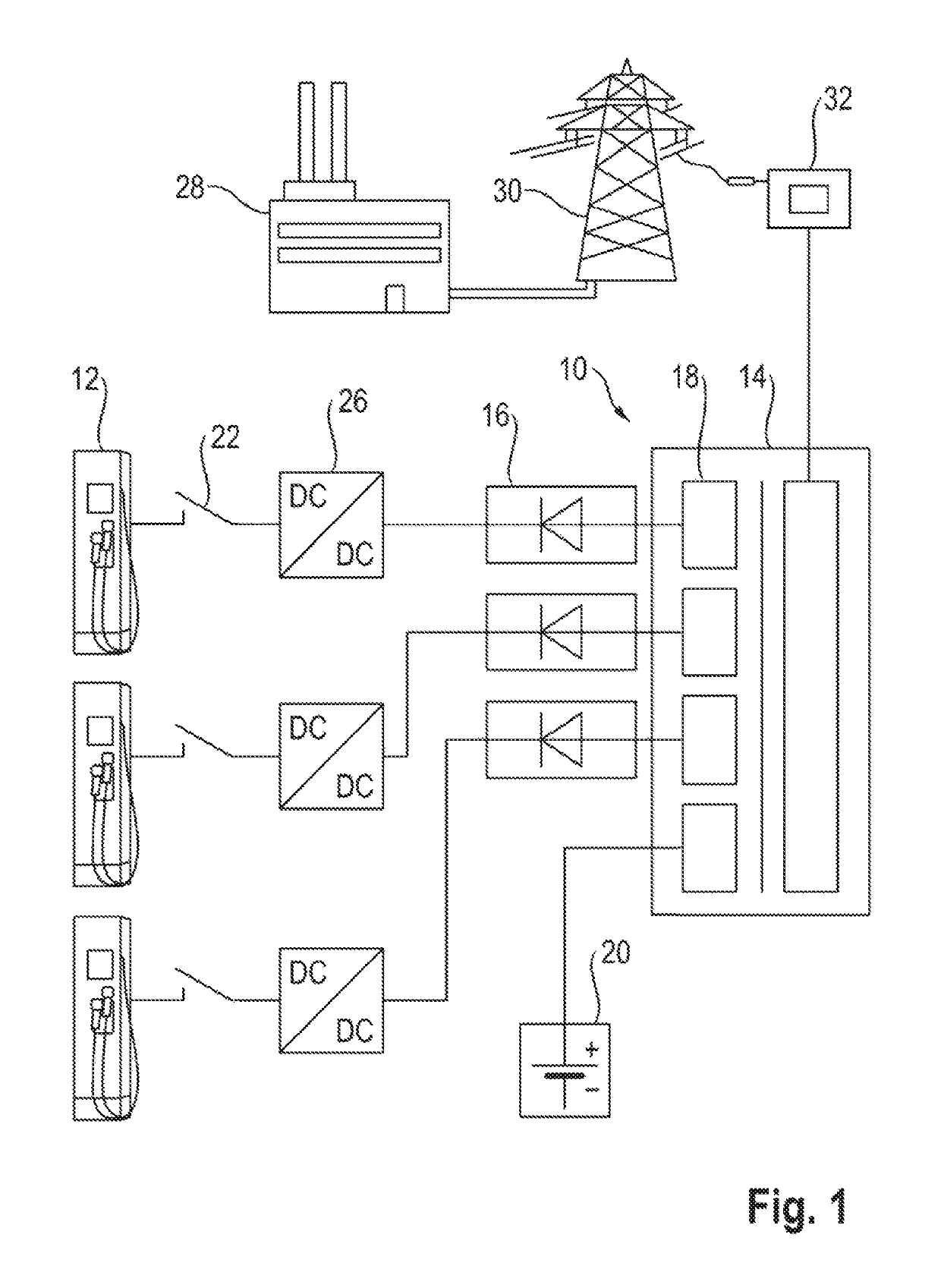
[0055]FIG. 1 shows the simplified design of a charging station 10 for charging at least one electrically operated vehicle, that is to say a plug-in vehicle at one of three charging posts 12. The charging station 10 comprises a power transformer 14 having an insulation monitor and safety measures. The power transformer 14 is fed with a medium voltage of 20 kV, for example, by an upstream transformer 32 of a medium-voltage grid. Said upstream transformer is in turn fed from a power plant 28 via an extra-high-voltage and high-voltage grid 30 operated with voltages of between 110 and 380 kV.

[0056]The charging station 10 is embodied as a central high-power AC / DC converter. The charging station 10 comprises three rectifier modules 16, which are connected to three DC-isolated terminal leads 18 of the power transformer 14 and are combined to form a multi-pole busbar, in order to provide an intermediate grid having a total power of 600 kW. A fourth terminal lead 18 is connected to a buffer s...


PUM


Abstract

A power electronics system for charging at least one electrically operated vehicle, wherein the power electronics system has at least two modules each having at least one terminal pair with DC output, at least one rectifier, at least one AC input, at least one DC link and a number of switching elements the switching elements are arranged at and / or between the DC outputs of the at least two modules in such a way that, between the at least two modules, at least one series and one parallel circuit configuration can be selectively dynamically set by suitable switching states of the switching elements.

Description

CROSS-REFERENCE TO RELATED APPLICATIONS[0001]This application claims priority to German Patent Application No. DE 10 2016 123 924.0, filed Dec. 9, 2016, the content of such application being incorporated by reference herein in its entirety.FIELD OF THE INVENTION[0002]The present invention relates to a modular power electronics system for charging at least one electrically operated vehicle at a charging post and to a corresponding method.BACKGROUND OF THE INVENTION[0003]Modern electric vehicles generally allow two charging modes. A vehicle has an on-board charging device for charging at a conventional AC voltage or three-phase socket, said charging device both performing the required conversion to direct current and controlling the respective charging operation. However, this AC charging mode is extremely restricted in terms of charging speed on account of the connection power available, which is generally not more than 16 A or 32 A, and on account of the installation of the charging...

Claims


Application Information

Patent Timeline
Patent Type & Authority Patents(United States)
IPC IPC(8): H02J7/00B60L53/22B60L53/60H02J7/02B60L3/00B60L53/30B60L53/10
CPCH02J7/022B60L53/20H02J7/34H02J2310/48H02J7/0013H02J7/0042B60L3/00B60L3/0092B60L2210/10B60L2210/30Y02T90/14B60L53/22B60L53/30B60L53/11H02J2207/20H02J2207/40B60L53/62B60L58/13B60L58/21B60L58/19H02J7/02Y02T10/7072Y02T10/72Y02T90/12Y02T10/70
Inventor GÖTZ, STEFANREBER, VOLKER
Owner DR ING H C F PORSCHE AG
Why Eureka
Try Eureka