

Methods for inhibiting solvent emissions
- Summary
- Abstract
- Description
- Claims
- Application Information
AI Technical Summary
Benefits of technology
Problems solved by technology
Method used
Image

Examples
first embodiment
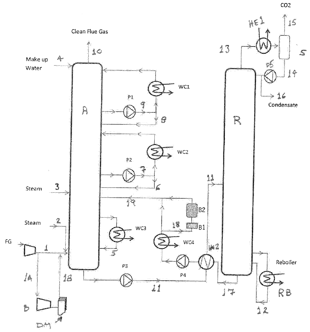
[0027]The present invention will manage aerosol emissions as well as reducing solvent loss by several techniques. In the first embodiment, steam is fed through line 2 into the flue gas stream containing carbon dioxide as it enters the absorber column A. The steam will condense on the submicron particles which will increase their density and size. The fine particles will increase in size and density until the gravity force becomes predominant and the particles fall into the solvent bulk. Further, when the flue gas stream is also high in SO3 content, steam injection will convert the SO3 in sulfuric acid droplets that can be condensed downstream in the absorber column A. The amount of steam is dictated by a delta approach to dew point. It is preferred to add low grade steam (LP steam of 4 to 8 bara) while keeping within the 10° C. approach to dew point.
[0028]With respect to the sulfuric acid, the amount produced is typically small and in the parts per million level. However, if an upst...
third embodiment
[0030]In a third embodiment, the flue gas stream that is fed via line 1 into the absorber column A is diverted through line 1A where it will enter a demister DM. Typically this demister is submicron and Brownian type where the fine particulate is captured before the flue gas stream is fed through line 1B back to line 1 for entry into the absorber column A. Due to additional pressure drop, a blower or steam ejector B may be required for feeding the flue gas stream into the demister DM. A Brownian demister will typically operate like other demisters with smaller opening area for gas acting as a filter. The pressure drop in this case can be quite significant which leads to an increase in the head pressure. A steam ejector could be employed if enough steam is available.
fourth embodiment
[0031]In the invention, reducing the temperature differential between the lean solvent inlet temperature at line 19 into column A and the immediate absorption section above the lean solvent inlet line 19 will reduce solvent aerosol emissions. Accordingly, the temperature of the lean solvent at its inlet is 50° to 55° C. due to the absorption heat when the carbon dioxide is absorbed in the lean solvent. Preferably, the lean solvent thus fed at these elevated temperatures can bypass the second stage inter-stage cooler WC2 as it flows upwards through the absorber column A. This results in the third inter-stage cooler not being necessary.
PUM
| Property | Measurement | Unit |
|---|---|---|
| Fraction | aaaaa | aaaaa |
Abstract
Description
Claims
Application Information