
Chuck mechanism

a chuck and mechanism technology, applied in the direction of gripping heads, metal-working machine components, manufacturing tools, etc., can solve the problems of inability to handle the gripping member, the gripping member cannot make surface contact with all pipes of various diameters, and the load may be concentrated excessively on the pipe being clamped, etc., to achieve the effect of simple structure, reduced device size and easy operation

Active Publication Date: 2018-04-26
SANOH IND CO LTD
View PDF11 Cites 5 Cited by
  • Summary
  • Abstract
  • Description
  • Claims
  • Application Information

AI Technical Summary

Benefits of technology

The chuck mechanism described in this patent uses a link mechanism to open and close, making it smaller and easier to handle pipes of different diameters. The clamp surfaces move parallel to the pipe, ensuring a secure grip without any damage to the surface. The technical effect is a more efficient and reliable chuck mechanism for pipe handling.

Problems solved by technology

The biggest issue with these chucks is that the open / close width of clamps is small so that the clamps cannot handle a variety of pipes ranging from small to large diameters, and the jaws or collets have to be changed in accordance with the pipe diameters.
However, since the gripping members of this chuck mechanism clamp a pipe by rotating around pivot axes, the gripping members cannot make surface contact with all of pipes of various diameters and sometimes make line contact, or point contact depending on the case.
Therefore the load may be concentrated excessively on the pipe being clamped and sometimes a dent or scar was formed on the pipe.

Method used


Image

  • Chuck mechanism
  • Chuck mechanism
  • Chuck mechanism

Examples


Embodiment Construction

[0025]Hereinafter, one embodiment of chuck mechanism according to the present invention will be described in detail with reference to the drawings.

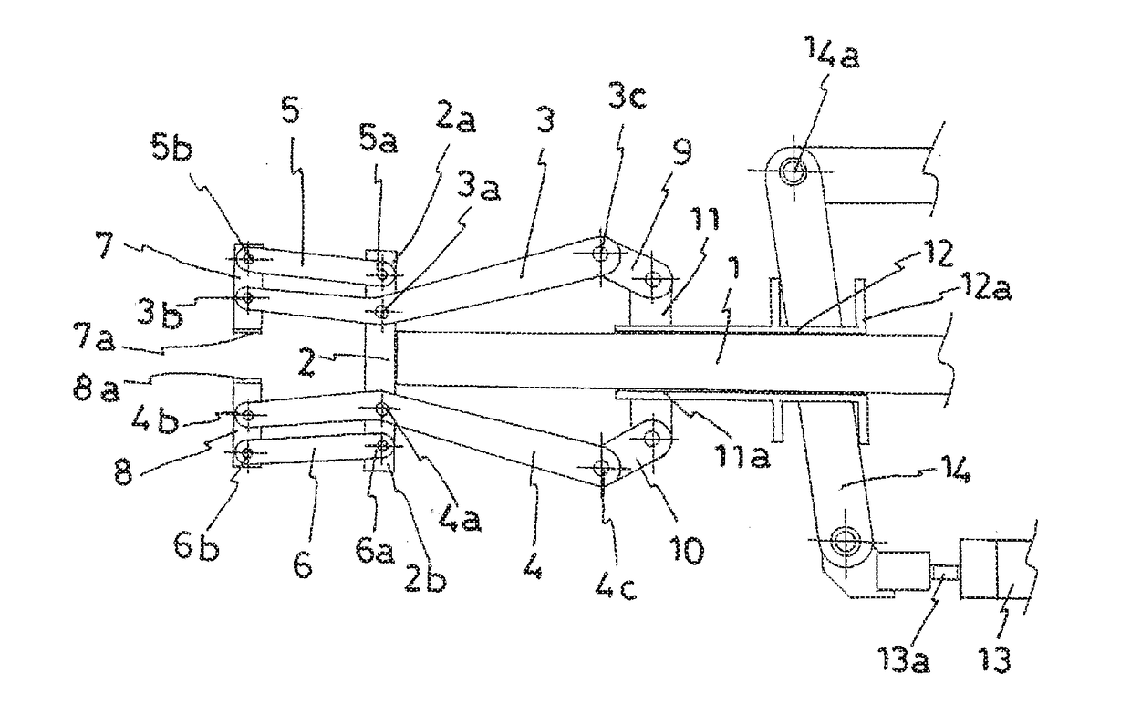
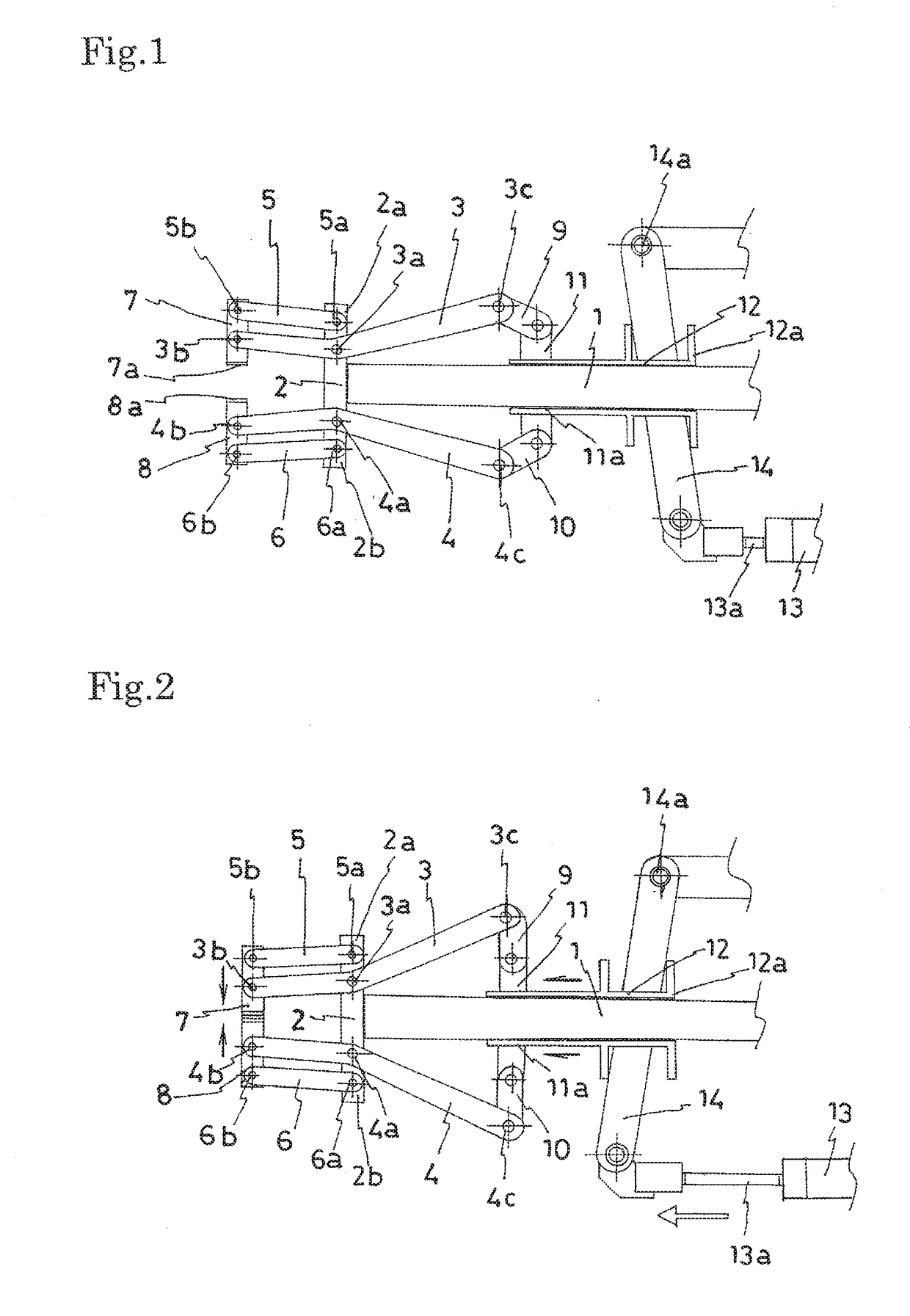
[0026]FIG. 1 and FIG. 2 are conceptual diagrams illustrating major parts of one embodiment of chuck mechanism according to the present invention. FIG. 1 and FIG. 2 are side views, respectively illustrating a state in which the chuck mechanism is open, and a state in which the chuck mechanism is closed.

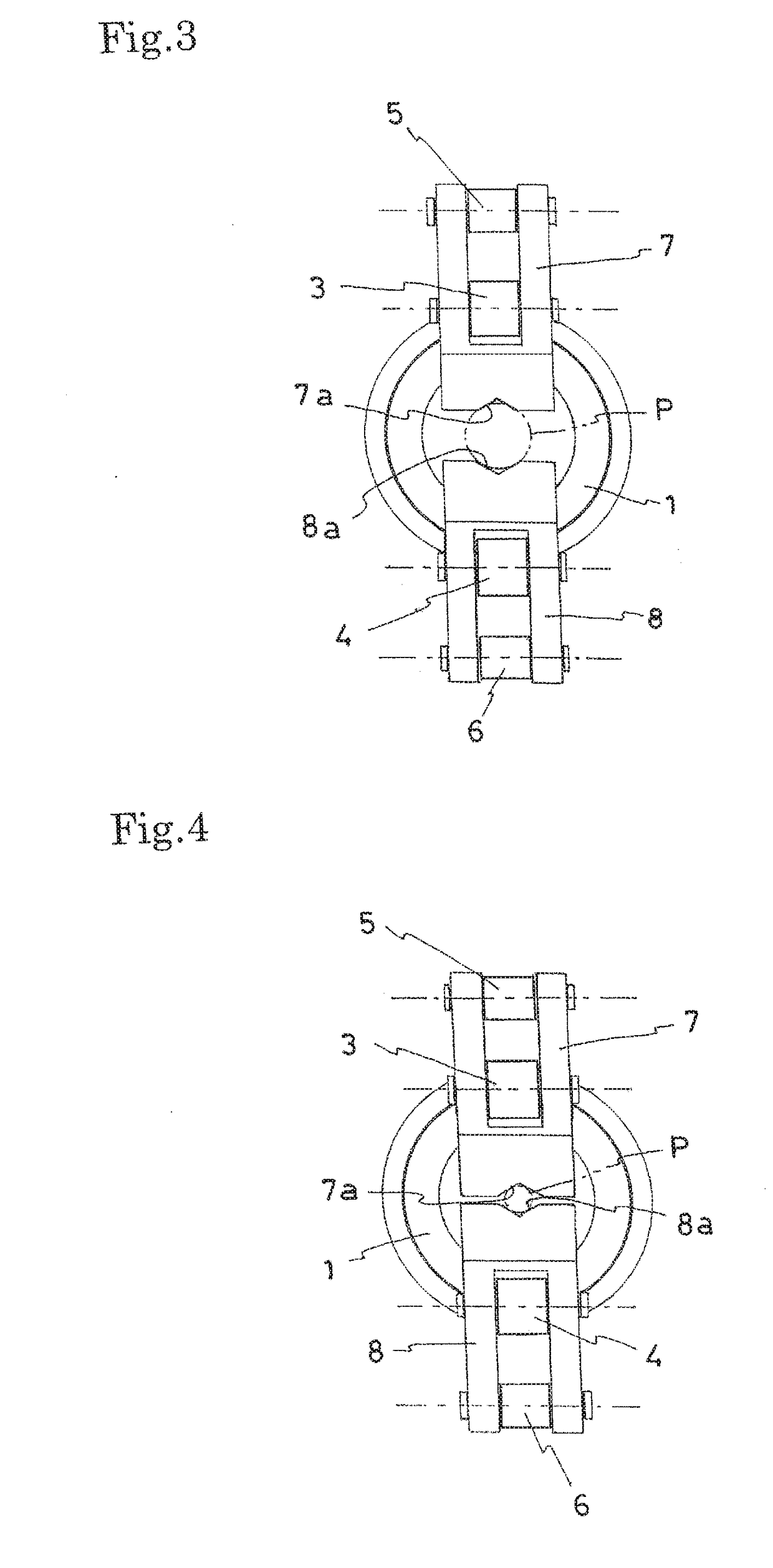
[0027]In these drawings, reference numeral 1 denotes a shaft that is arranged horizontally, and 2 denotes a frame provided at a distal end of the shaft 1 and protruding in the up and down direction of the shaft 1. To an upper part 2a and a lower part 2b of the frame 2, are provided, respectively, a pair of dog leg shaped link members 3 and 4 having bent portions 3a and 4a protruded inward and swingably supported at the respective bent portions 3a and 4a, and at parallel link members 5 and 6 having respectively rear ends 5a and 6a rotatably s...


PUM

PropertyMeasurementUnit
torqueaaaaaaaaaa
diametersaaaaaaaaaa
structureaaaaaaaaaa

Abstract

A chuck mechanism enables downsizing of the device with a simple structure, has a wide open / close width of clamps, and hardly causes a dent or scar on pipes. The chuck mechanism includes a horizontally arranged shaft, a frame, a pair of dog leg shaped link members, parallel link members, a pair of clamp members, and a swing drive mechanism.

Description

TECHNICAL FIELD[0001]The present invention relates to a chuck mechanism, and more particularly to a chuck mechanism used for clamping pipes during pipe processing such as cutting and bending.BACKGROUND ART[0002]Three-jaw chucks or collet chucks have been widely used as clamps for pipes in pipe processing such as cutting and bending. The biggest issue with these chucks is that the open / close width of clamps is small so that the clamps cannot handle a variety of pipes ranging from small to large diameters, and the jaws or collets have to be changed in accordance with the pipe diameters.[0003]Meanwhile, there are chucks with a pair of gripping members each having one end pivotally supported and arranged in an inverted V shape. The gripping members are opened and closed by rotating the gripping members around the pivot axes (PTL 1, for example). The open / close width of clamps of this chuck mechanism can be made larger easily, and the clamps can be designed to be capable of handling pipe...

Claims


Application Information

Patent Timeline
Patent Type & Authority Applications(United States)
IPC IPC(8): B23Q3/06B23Q7/04B25J15/10
CPCB23Q3/064B23Q7/047B25J15/10B23Q7/04B23Q2240/007B25B27/023Y10T29/5387
Inventor LAN, GUANG PING
Owner SANOH IND CO LTD
Learn More