
Gyro-based surveying tool and method for surveying

a surveying tool and gyro-based technology, applied in the direction of surveying, navigation by speed/acceleration measurement, wellbore/well accessories, etc., can solve the problems drifting, and gyroscopes can, however, can solve the problem of increasing the uncertainty of surveying, so as to improve improve cost-saving aspects , the effect of improving the accuracy of surveying tools

Active Publication Date: 2018-04-26
LKAB WASSARA AB
View PDF38 Cites 4 Cited by
  • Summary
  • Abstract
  • Description
  • Claims
  • Application Information

AI Technical Summary

Benefits of technology

The invention aims to improve the accuracy and reduce the cost of surveying, especially while drilling. The analysis unit uses a signal modelling model that takes into account the characteristics of the MEMS-IMU arrangements. This model, which is based on a Markov chain model, especially a first order Markov chain model, helps to account for the influence of noise and reduces the impact of non-consecutive measurements. This results in more accurate surveying while drilling.

Problems solved by technology

Gyroscopes can, however, drift and this drift will add over time.
This leads to the fact that in general the longer a gyroscope is used the more will the uncertainty of the surveying be.
Such gyroscopes are, however, due to their complexity and / or due to their need of especially careful assembling / manufacturing only available at a relatively high cost.
This makes them impossible to use in slim-hole configurations often requiring a diameter of less than 38 mm for the surveying and / or drilling equipment.

Method used


Image

  • Gyro-based surveying tool and method for surveying
  • Gyro-based surveying tool and method for surveying
  • Gyro-based surveying tool and method for surveying

Examples


Embodiment Construction

[0043]Throughout this document the term “bore hole” can relate to both a drilled hole and a drilling hole. In one example, the term “basically vertically” relates to a vertical direction which can deviate up to six degrees (out of a 360 degrees full circle) from the vertical direction. In one example, the term vertical comprises vertical upwards. In one example, the term vertical comprises vertical downwards.

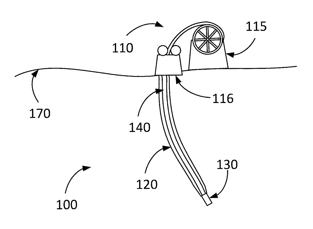
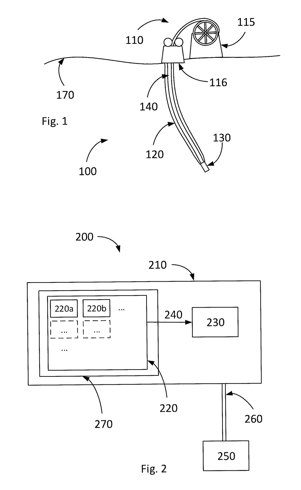
[0044]FIG. 1 shows a schematic example of a situation in which the present disclosure can be used. It should be emphasized that the shown example is not to scale. In FIG. 1 a soil 170 is shown. A drilling arrangement 100 is shown for drilling a drilling hole 120. The drilling hole can, for example, be a bore hole or a wellbore. In one example, the drilling arrangement 100 is a coiled tubing, CT, drilling arrangement. The drilling arrangement 100 can comprise a tube 140. One part of the tube 140 can be in the drilling hole 120 and another part of the tube 140 can be outside the d...


PUM


Abstract

The present disclosure relates to a gyro-based surveying tool for surveying of holes oriented in a basically vertical direction in areas with no line-of-sight connection to the sky. The gyro-based surveying tool comprises a surveying head and an analysing unit. The surveying head comprises a plurality of MicroElectroMechanical-systems-inertial-measurement-unit arrangements, MEMS-IMU arrangements. Each of the MEMS-IMU arrangements is arranged to transmit information relating to their measurement results to the analysing unit. The analysing unit is arranged to receive and analyse said transmitted information relating to the measurement results from the plurality of MEMS-IMU arrangements so as to calculate a combined measurement result. The surveying tool further comprises means for calculating an attitude and / or position of said surveying head based on said combined measurement result.The present disclosure also relates to a surveying method, a computer program for surveying, and a computer program product.

Description

TECHNICAL FIELD[0001]The disclosure relates to a gyro-based surveying tool for surveying of holes oriented in a basically vertical direction in areas with no line-of-sight connection to the sky, to a surveying method, to a computer program and to a computer program product.BACKGROUND ART[0002]When surveying it is common to use surveying tools which work with the help of global navigation satellite systems, GNSS. These surveying tools demand, however, a line of sight to the sky so that signals from the satellites can be received without being damped too much. When surveying areas or spaces without line-of-sight connection to the sky thus other means have to be used for surveying. This is especially important when surveying inside mountains or in holes. Such surveying inside mountains is for example important in tunnelling or mining. Such surveying inside holes is for example important for drilling holes, geothermal holes, mining holes, oil holes, gas holes, or the like. Other kinds o...

Claims


Application Information

Patent Timeline
IPC IPC(8): E21B47/09E21B47/022B81B7/02
CPCE21B47/09E21B47/022B81B7/02B81B2201/0242E21B47/00G01C21/16E21B44/00E21B47/024G01C21/165
Inventor PECO, THIMAQ TIMHULDEN, JARL
Owner LKAB WASSARA AB
Learn More