Light-emitting diode filament with a heat-dissipating structure and light-emitting diode filament light bulb using the same

Active Publication Date: 2018-04-26
LIQUIDLEDS LIGHTING
View PDF4 Cites 10 Cited by
  • Summary
  • Abstract
  • Description
  • Claims
  • Application Information

AI Technical Summary

Benefits of technology

[0004]An objective of the present invention is to provide a light-emitting diode (LED) filament and an LED filament light bulb

Problems solved by technology

However, heat generated by the multiple LED chips 91 during a light-emitting process gets accumulated inside the package layer 93 and fails to be effectively dissipated due to

Method used


Image

  • Light-emitting diode filament with a heat-dissipating structure and light-emitting diode filament light bulb using the same
  • Light-emitting diode filament with a heat-dissipating structure and light-emitting diode filament light bulb using the same
  • Light-emitting diode filament with a heat-dissipating structure and light-emitting diode filament light bulb using the same

Examples


first embodiment

[0038]With reference to FIG. 5, the LED filament mounted inside an LED filament light bulb as illustrated is described as follows.

[0039]The LED filament light bulb includes a base 61, an insulating mount 62, the foregoing first LED string 10, multiple tie wires 63 and a seal glass bulb 64.

[0040]The base 61 has an electrical foot contact 611 and a screw thread contact 612. The electrical foot contact 611 is formed on a bottom of the base 61. The screw thread contact 612 is formed around a peripheral wall of the base 61. The electrical foot contact 611 and the screw thread contact 612 are used to electrically connect to an external power source. In the present embodiment, the electrical foot contact 611 and the screw thread contact 612 are respectively connected to a positive electrode and a negative electrode of the external power source.

[0041]The insulating mount 62 is formed on a top of the base 61. In the present embodiment, the insulating mount 62 is made of glass and has a mount...

fourth embodiment

[0046]Each of the third LED string 10B and the fourth LED string 10C includes multiple LED chips 11B, 11C, multiple conductive carriers 12B, 12C and a package layer, which are structurally similar to the multiple LED chips 11, 11A, the multiple conductive carriers 12, 12A and the package layer of each of the first LED string 10 and the second LED string 10A. The materials of forming the multiple LED chips 11B, 11C, the multiple conductive carriers 12B, 12C and the package layer of each of the third LED string 10B and the fourth LED string 10C are identical to those of each of the first LED string 10 and the second LED string 10A. To keep description associated with the fourth embodiment concise, structural description of the present embodiment similar to that of the foregoing embodiments is not elaborated here.

[0047]The highest ones of the multiple conductive carriers 11, 11A, 11B, 11C of the first LED string 10, the second LED string 10A, the third LED string 10B and the fourth LED...


PUM


Abstract

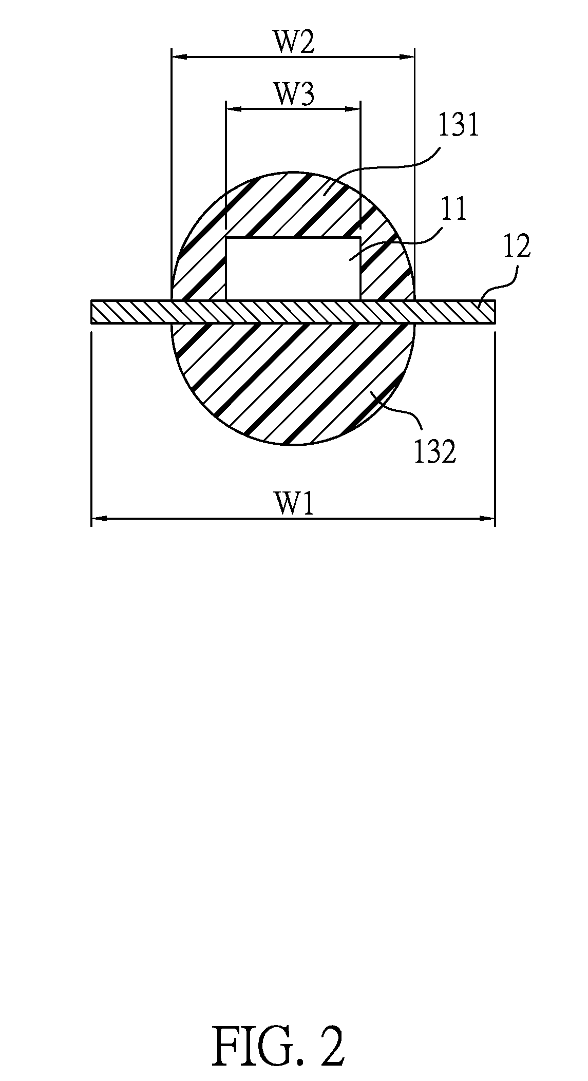
A light-emitting diode (LED) filament with a heat-dissipating structure includes multiple LED chips, multiple conductive carriers and a package layer. Each conductive carrier takes the form of a metal sheet and the multiple conductive carriers are spaced apart from each other. Each LED chip is commonly carried by and is electrically connected to two of the multiple conductive carriers adjacent to the LED chip. The package layer covers the multiple LED chips and the multiple conductive carriers with two lateral edge portions of each conductive carrier exposed from the package layer. The LED filament is mounted inside a light bulb. Because the multiple conductive carriers are partially exposed from the package layer, heat generated by the multiple LED chips can be dissipated to an ambient environment without affecting lighting efficiency and light output as a result of accumulated heat.

Description

BACKGROUND OF THE INVENTION1. Field of the Invention[0001]The present invention relates to a filament and, more particularly, to a light-emitting diode (LED) filament with a heat-dissipating structure and an LED filament light bulb using the same.2. Description of the Related Art[0002]Rapid development of lighting technology gives rise to a variety of LED lighting products. A kind of vintage light bulb simulating incandescent light bulbs has been introduced to the lighting market recently. Such vintage light bulb includes one or more LED filaments mounted inside a light bulb and exhibiting the effect of the filament in a conventional incandescent light bulb to render the vintage light bulb with a retro look.[0003]With reference to FIGS. 8 and 9, a conventional LED filament 90 includes multiple LED chips 91, multiple conductive carriers 92 and a package layer 93. Each LED chip 91 is commonly supported by and is electrically connected in series to two of the multiple conductive carrie...

Claims


Application Information

Patent Timeline
IPC IPC(8): F21K9/232F21V23/00F21K9/238
CPCF21K9/232F21V23/002F21K9/238F21Y2115/10F21Y2107/00F21V29/503H01L33/54H01L33/62H01L33/64H01L25/0753H01L33/48H01L33/647
Inventor HUANG, DAVID
Owner LIQUIDLEDS LIGHTING
Why Eureka
Try Eureka