Shaped light guide illumination devices

a technology of illumination devices and light guides, applied in the direction of illuminated signs, display means, instruments, etc., can solve the problems of difficult control of angular distribution, limitations of conventional edge-lit illumination systems,

Active Publication Date: 2018-04-26
S V V TECH INNOVATIONS
View PDF2 Cites 32 Cited by
  • Summary
  • Abstract
  • Description
  • Claims
  • Application Information

AI Technical Summary

Benefits of technology

[0011]The invention will be more fully understood by reference...

Problems solved by technology

The conventional edge-lit illumination systems may exhibit cer...

Method used


Image

  • Shaped light guide illumination devices
  • Shaped light guide illumination devices
  • Shaped light guide illumination devices

Examples


Embodiment Construction

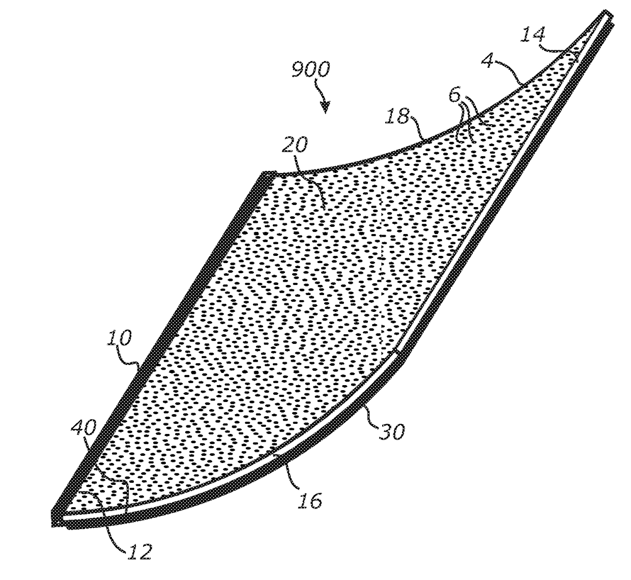
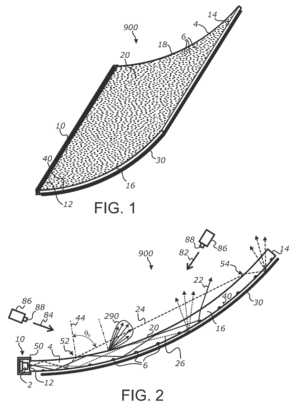
[0036]Referring more specifically to the drawings, for illustrative purposes the present invention is embodied in the system generally shown in the preceding figures. It will be appreciated that the system may vary as to configuration and as to details of the parts without departing from the basic concepts as disclosed herein. Furthermore, elements represented in one embodiment as taught herein are applicable without limitation to other embodiments taught herein, and in combination with those embodiments and what is known in the art.

[0037]A wide range of applications exists for the present invention in relation to the collection and distribution of electromagnetic radiant energy, such as light, in a broad spectrum or any suitable spectral bands or domains. Therefore, for the sake of simplicity of expression, without limiting generality of this invention, the term “light” will be used herein although the general terms “electromagnetic energy”, “electromagnetic radiation”, “radiant en...


PUM


Abstract

A shaped illumination panel having a broad-area sheet-form configuration and including a flexible sheet of an optically transmissive material and one or more light sources optically coupled to an edge of the flexible sheet. The flexible sheet may include forward-deflecting or forward-scattering elements configured to extract light from one location of the flexible sheet and direct the extracted light to a second location of the flexible sheet where the extracted light can be transversely propagated through and reemitted from the flexible sheet.

Description

CROSS-REFERENCE TO RELATED APPLICATIONS[0001]This application claims priority from U.S. provisional application Ser. No. 62 / 412,596 filed on Oct. 25, 2016, incorporated herein by reference in its entirety.STATEMENT REGARDING FEDERALLY SPONSORED RESEARCH OR DEVELOPMENT[0002]Not ApplicableINCORPORATION-BY-REFERENCE OF MATERIAL SUBMITTED ON A COMPACT DISC[0003]Not ApplicableNOTICE OF MATERIAL SUBJECT TO COPYRIGHT PROTECTION[0004]A portion of the material in this patent document is subject to copyright protection under the copyright laws of the United States and of other countries. The owner of the copyright rights has no objection to the facsimile reproduction by anyone of the patent document or the patent disclosure, as it appears in the United States Patent and Trademark Office publicly available file or records, but otherwise reserves all copyright rights whatsoever. The copyright owner does not hereby waive any of its rights to have this patent document maintained in secrecy, inclu...

Claims


Application Information

Patent Timeline
IPC IPC(8): F21V8/00G09F13/02G09F13/18
CPCG02B6/002G09F13/02G09F13/18G02B6/0031G02B6/0088G09F2013/222G02B6/0053G02B6/0055G02B6/0028G02B6/0036G02B6/0043G02B6/0046G02B6/0061
Inventor VASYLYEV, SERGIY
Owner S V V TECH INNOVATIONS
Why Eureka
Try Eureka