Mobile vehicle and wireless power transfer system

a wireless power transfer and mobile vehicle technology, applied in the direction of charging stations, battery/cell propulsion, transportation and packaging, etc., can solve the problems of affecting the power supply affecting the operation of the mobile vehicle, and the power reception electrode may come into contact with the obstacle, so as to achieve safe transfer

Active Publication Date: 2018-04-26
PANASONIC INTELLECTUAL PROPERTY MANAGEMENT CO LTD
View PDF1 Cites 5 Cited by
  • Summary
  • Abstract
  • Description
  • Claims
  • Application Information

AI Technical Summary

Benefits of technology

[0006]According to the technique of the present disclosure, power can be safely transferred in a situation where an obstacle exists on the po

Problems solved by technology

In the wireless power transfer system using the electric field coupling technique, when an obstacle exists on the power transmission electrodes, the power

Method used


Image

  • Mobile vehicle and wireless power transfer system
  • Mobile vehicle and wireless power transfer system
  • Mobile vehicle and wireless power transfer system

Examples


embodiment 1

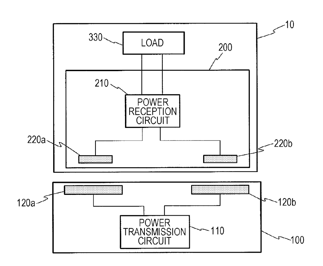
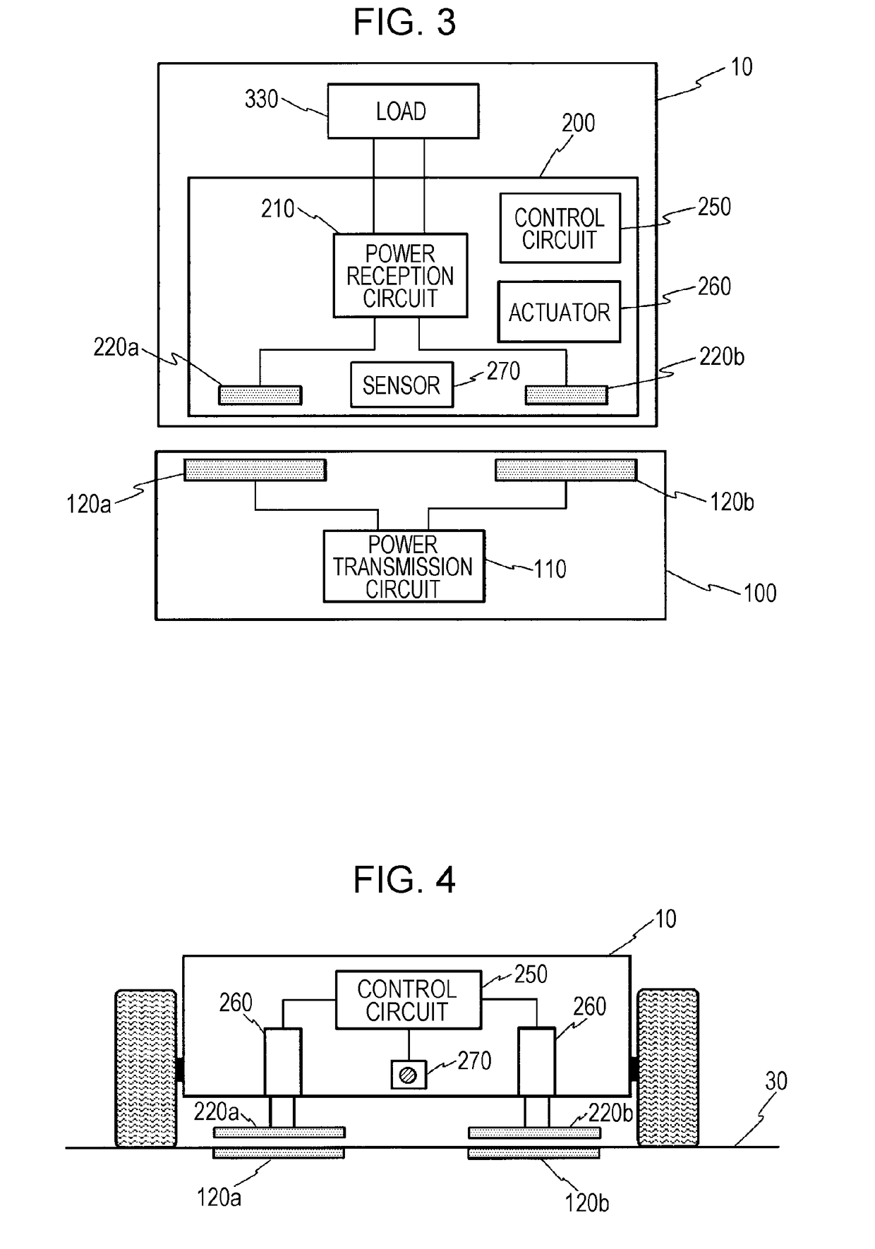
[0081]FIG. 3 is a diagram illustrating a schematic configuration of a wireless power transfer system in Embodiment 1 of the present disclosure. In the system illustrated in FIG. 3, as in the system illustrated in FIGS. 1 and 2, electric power is wirelessly transferred from a power transmission device 100 including a pair of power transmission electrodes 120a, 120b laid below or on a road surface, to a conveyance robot 10 including a pair of power reception electrodes 220a, 220b. The wireless power transfer system in the embodiment is different from the system illustrated in FIG. 2 mainly in that the power reception electrodes 220a, 220b in the conveyance robot 10 are driven by an actuator 260.

[0082]As illustrated in FIG. 3, a power reception device 200 of the conveyance robot 10 in the embodiment includes a sensor 270, the actuator 260, and a control circuit 250, in addition to the power reception electrodes 220a, 220b and a power reception circuit 210. The sensor 270 in the embodim...


PUM


Abstract

A mobile vehicle wirelessly receives AC power from a power transmission device including first and second power transmission electrodes arranged along a road surface. The mobile vehicle includes: a sensor that detects an obstacle located at least either on a route of the mobile vehicle or under the mobile vehicle; a first power reception electrode that forms electric field coupling with the first power transmission electrode when facing the first power transmission electrode; a second power reception electrode that forms electric field coupling with the second power transmission electrode when facing the second power transmission electrode; an actuator that moves at least the part of the first power reception electrode in a direction of gravity; and a control circuit that controls the actuator based on a result of detection by the sensor to avoid contact between the first power reception electrode and the obstacle.

Description

BACKGROUND1. Technical Field[0001]The present disclosure relates to a mobile vehicle driven by electric power transferred wirelessly and to a wireless power transfer system.2. Description of the Related Art[0002]In recent years, wireless power transfer techniques for wirelessly transferring electric power to a mobile device such as a mobile phone and an electric car have been developing. The wireless power transfer techniques include techniques such as an electromagnetic induction technique and an electric field coupling technique. In a wireless power transfer system using the electric field coupling technique out of these techniques, alternating current (AC) power is wirelessly transferred from a pair of power transmission electrodes to a pair of power reception electrodes with the pair of power transmission electrodes and the pair of power reception electrodes facing each other. Such a wireless power transfer system using the electric field coupling technique can be used to, for e...

Claims


Application Information

Patent Timeline
IPC IPC(8): H02J50/60B60L11/18H02J50/10H02J50/90
CPCH02J50/60B60L11/182B60L2240/10H02J50/90H02J7/025H02J50/10H02J50/05B60L9/00B60L2200/44B60L2240/64B60L2260/42B60L50/53B60L53/124B60L53/126Y02T10/70Y02T10/7072Y02T90/14Y02T10/72Y02T90/16Y02P90/60B60L5/38B60L53/12
Inventor KANNO, HIROSHI
Owner PANASONIC INTELLECTUAL PROPERTY MANAGEMENT CO LTD
Why Eureka
Try Eureka