Variable Circulation Rate Sub for Delivering a Predetermined Straight through Flow

Inactive Publication Date: 2018-05-03
BAKER HUGHES INC
View PDF3 Cites 3 Cited by
  • Summary
  • Abstract
  • Description
  • Claims
  • Application Information

AI Technical Summary

Benefits of technology

[0004]A housing is integrated into a tubing string having a straight through passage and a lateral wall. Inside the passage is a flow responsive member with a preload force applied to it. Flow corresponding to a predetermined pressure difference in the housing will not move the valve member, so all flow will go straight through in a downhole direction. As flow increases, the preload bias is overcome to align the passage through

Problems solved by technology

Automatic systems have been developed to accomplish this task

Method used


Image

  • Variable Circulation Rate Sub for Delivering a Predetermined Straight through Flow
  • Variable Circulation Rate Sub for Delivering a Predetermined Straight through Flow

Examples


Example

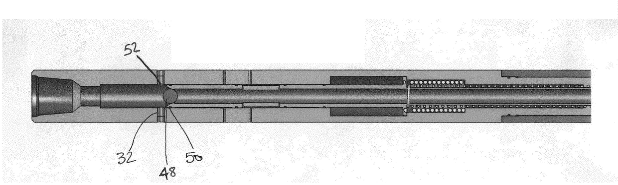
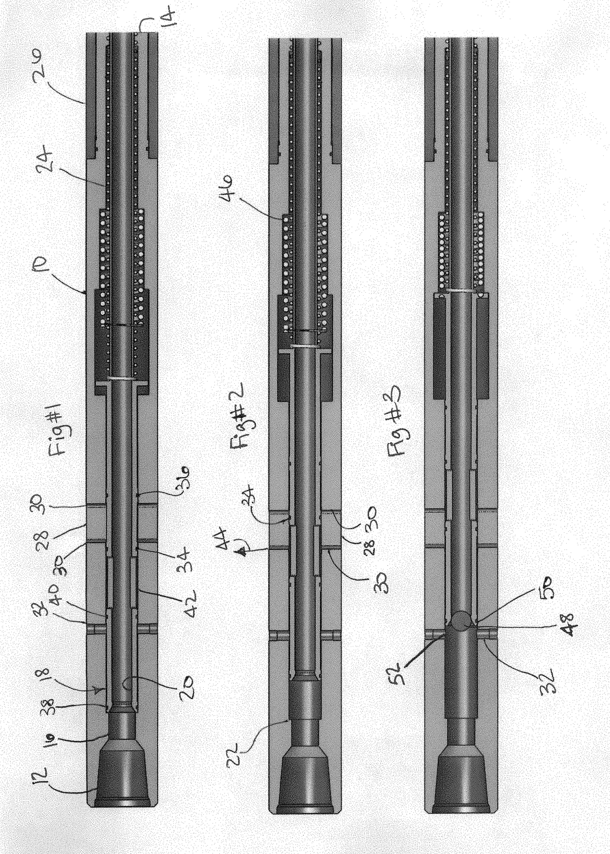
[0008]Referring to FIG. 1, a housing 10 with an uphole connection 12 to a tubular string that is not shown. A downhole end 14 can be connected to a bottom hole assembly for drilling that is also not shown. For a number of reasons, the bottom hole assembly that is not shown needs a predetermined flow rate out the downhole end 14. Flow coming into uphole end 12 enters passage 16 where a valve member 18 is located that has flow path 20 therethrough that aligns with passage 16. Housing 10 has an internal shoulder 22 that acts as an uphole travel stop for the valve member 18 under the bias of a stored force. In this case, the preferred mode for the force is a coiled spring 24. Sleeve 26 schematically illustrates a device that can be used to change the preload on spring 24 which has the effect of changing the amount of flow coming into uphole end 12 that will go straight through to downhole end 14 without being circulated through openings 28, 30 or 32. In the FIG. 1 position openings 28 a...


PUM


Abstract

A housing is integrated into a tubing string having a straight through passage and a lateral wall exist. Inside the passage is a flow responsive member with an applied preload force. Flow corresponding to a predetermined differential pressure in the housing will not move the valve member so all flow will go straight through in a downhole direction. As flow increases, the preload bias is overcome to align the passage through the housing and openings in the valve member with wall openings. As flow into the housing increases, more lateral wall opening area is aligned with the passage to increase circulation flow while holding through flow downhole constant. Dropping a ball on the valve member blocks through flow and allows opening of total bypass passages. The ball can be removed by blowing it through the seat or otherwise failing or disintegrating it.

Description

FIELD OF THE INVENTION[0001]The field of the invention is downhole circulation subs and more particularly subs that vary circulation rate to hold a predetermined straight through flow responsive to incoming flow and with a capability to be selectively placed in full recirculation or automatic recirculation modes.BACKGROUND OF THE INVENTION[0002]In drilling operations it is sometimes necessary to deliver a predictable flow rate to a mud motor, directional drilling equipment or the bit. Automatic systems have been developed to accomplish this task but they are complex and very expensive to install and operate. One example of such a system that sequentially opens and closes surface mounted choke valves is described in WO2015 / 179408 beginning at paragraph 53. Systems with similar complexity are described in U.S. Pat. No. 7,353,887. On the other hand, very basic systems that detect fluid loss during drilling and which rely on differential pressure measurements are revealed in U.S. Pat. N...

Claims


Application Information

Patent Timeline
IPC IPC(8): E21B34/10
CPCE21B34/10E21B21/103E21B2034/007E21B2200/06
Inventor HERED, WILLIAM A.HOLLOWAY, JAMES L.OBERG, LEVI B.
Owner BAKER HUGHES INC
Why Eureka
Try Eureka