Connection structure of integrated panel and fluid device

A technology of integrated panel and connection structure, applied in the direction of sealing surface connection, flange connection, pipe components, etc., can solve the problems of bolt fastening force reduction, joint leakage, high fastening force, etc., and achieve excellent sealing performance and assembly Improved operability and good sealing effect

Inactive Publication Date: 2008-07-16
NIPPON PILLAR PACKING CO LTD
View PDF2 Cites 3 Cited by
  • Summary
  • Abstract
  • Description
  • Claims
  • Application Information

AI Technical Summary

Problems solved by technology

However, the tightening force of the bolts will inevitably decrease over time. Therefore, regular tightening must be performed to prevent leakage at the joint caused by a decrease in the tightening force, that is, a decrease in torque.
In the case of

Method used


Image

  • Connection structure of integrated panel and fluid device
  • Connection structure of integrated panel and fluid device
  • Connection structure of integrated panel and fluid device

Examples


Embodiment 1

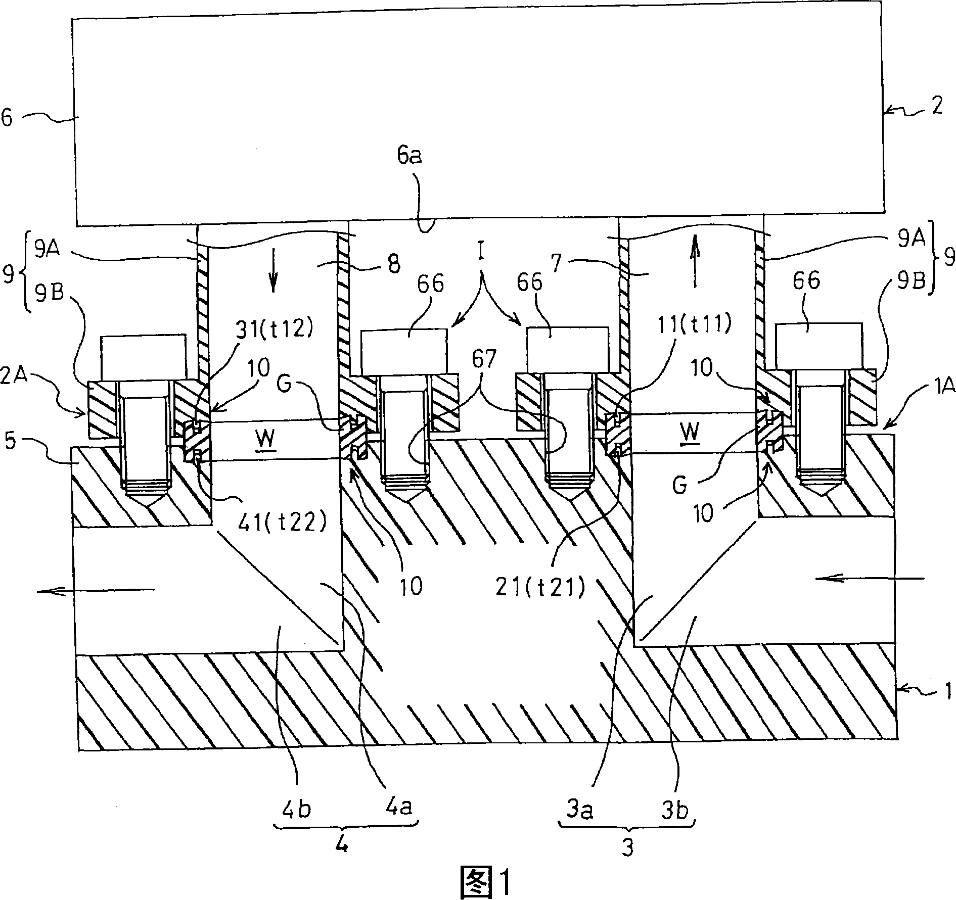
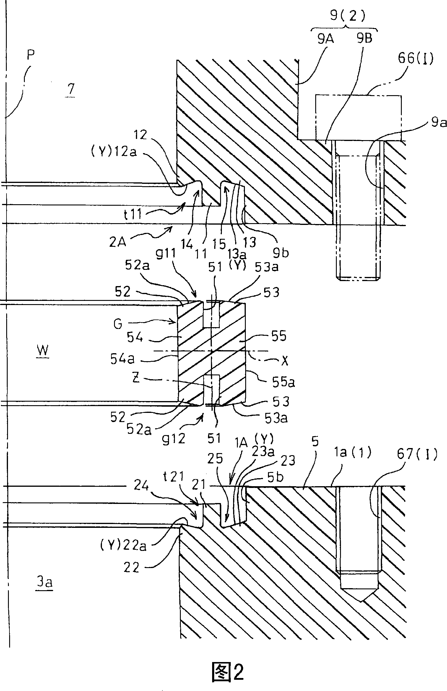
[0114] Fig. 1 and Fig. 2 show the connection structure between the integrated panel and the fluid device in the first embodiment. The connection structure between the integrated panel and the fluid device is an integrated panel 1 with a pair of circular tubular fluid channels 3, 4 formed inside and an annular gasket G mounted on the upper surface 1a of the integrated panel 1. Valves (on-off valves, stop valves, etc.) 2 constitute a single-flow path structure that shares the longitudinal axis P. That is, a pair of connecting structures for the supply row adopts the same structure as each other.

[0115] As shown in Figures 1 and 2, the structure of the integrated panel 1 is that a longitudinal flow opening on the upper surface 1a of the panel is formed inside a plate (or block) 5 made of fluororesin such as PFA or PTFE. A pair of circular tube-shaped supply-side fluid passages 3, 4 constituted by passages 3a, 4a and lateral flow passages 3b, 4b. The opening part of the fluid ...

Embodiment 2

[0141] FIG. 4 shows the connection structure between the integrated panel and the fluid device of the second embodiment. This is a structure for connecting the integrated panel 1 with an example of a fluid device—the filter 2 , and the connection structure itself is the same as that of Embodiment 1 shown in FIGS. 1 to 3 . Therefore, the same reference numerals are attached to the same positions, and descriptions thereof are omitted.

[0142] The filter 2 is composed of a main body case 2K, a lower case 2B, and a filter body 2C. The lower case 2B is formed with a supply-side fluid flow path 7, a discharge-side fluid flow path 8, and in a state having these fluid flow paths 7, 8. A pair of mounting flanges 9, 9 protrude laterally. These mounting flanges 9, 9 are communicated with the integrated panel 1 via a gasket G.

Embodiment 3

[0144] As shown in FIG. 5 , the connection structure between the integrated panel and the fluid device in Embodiment 3 is an example of the integrated panel 1 and the fluid device—that is, the connection structure of the regulator 2 . The regulator 2 includes a housing 2C composed of an upper case, an intermediate case, and a lower case. A bellows (not shown) clamped at the peripheral portion is accommodated between the upper case and the middle case. A valve body (not shown) whose peripheral part is clamped is accommodated between the box body and the lower box body, and a return spring (not shown) is accommodated in the lower box body.

[0145] A pair of mounting flanges 9 , 9 protruding laterally is integrally mounted on the casing 2C, and the regulator 2 is connected to the upper surface 1 a of the integrated panel 1 via the gasket G by using these mounting flanges 9 , 9 . The connection structure between the mounting flange 9 and the upper surface 1 a of the integrated pa...


PUM


Abstract

A connection structure of a stack panel to a fluid device capable of maintaining excellent sealability without almost performing further tightening and improving assemblability. The stack panel (1) is communicably connected to a valve (2) through an annular gasket (G) in such a state that a single cylindrical fluid passage (3, 7) is sealed. Annular projections (11) and (21) are formed at first and second fluid inlet and outlet parts (1A) and (2A), and the gasket (G) is formed of a fluororesin and comprises a pair of annular grooves (51) and (51) formed in the outer diameter portion of a fluid route (W) to be fitted to the annular projections (11) and (21). The stack panel (1) and the valve (2) are pulled to each other and the annular projections (11) and (21) of the first and second fluid inlet and outlet parts (1A) and (2A) are fitted to the annular grooves (51) of the gasket (G) to form a fitted seal part. The connection structure further comprises a maintaining means (I) for maintaining the connected state of the stack panel to the valve.

Description

technical field [0001] The present invention relates to a connection structure of an integrated panel and a fluid device, in detail, to a connection structure to be used in manufacturing processes in various technical fields such as semiconductor manufacturing, medical and pharmaceutical manufacturing, food processing, and chemical engineering In the pipeline system of high-purity liquid, ultrapure water, or cleaning liquid, etc., fluids that are expected to be needed in the future are connected with fluid components such as pumps, valves, and reservoirs in a sealed state through gaskets. Background technique [0002] The known above-mentioned connection structures include, for example, the connection structures disclosed in Patent Document 1 and Patent Document 2, which connect a pair of supply and discharge pipes to each other, and connect an example of a fluid device—a valve with an integrated panel with a fluid flow channel formed inside connect them. The connection str...

Claims


Application Information

Patent Timeline
IPC IPC(8): F16L39/00F16L19/03F16L23/04F16L23/16F16L41/08
Inventor 桂将义
Owner NIPPON PILLAR PACKING CO LTD
Why Eureka
Try Eureka