
High Shear Emulsifier

A high-shear emulsification machine and emulsification tank technology, applied in the field of emulsification equipment, can solve the problems of long working hours, low work efficiency, and small shear force, and achieve the effect of increasing shear force and circulation flow

Active Publication Date: 2016-03-09
ANHUI SONGYU ENG TECH EQUIP
View PDF7 Cites 3 Cited by
  • Summary
  • Abstract
  • Description
  • Claims
  • Application Information

AI Technical Summary

Problems solved by technology

[0003] However, the shear force of the current emulsifiers is relatively small, resulting in long working hours, low work efficiency, and waste of manpower and material resources.

Method used


Image

  • High Shear Emulsifier
  • High Shear Emulsifier

Examples


Embodiment Construction

[0014] In order to make it easy to understand the technical means, creative features, work flow, and use methods of the present invention to achieve the purpose and effect, the technical solutions in the embodiments of the present invention will be clearly and completely described below in conjunction with the embodiments of the present invention. Obviously, the The described embodiments are only some, not all, embodiments of the present invention. Based on the embodiments of the present invention, all other embodiments obtained by persons of ordinary skill in the art without making creative efforts belong to the protection scope of the present invention.

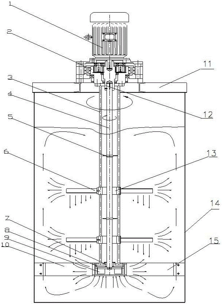
[0015] Such as figure 1 As shown, the high-shear emulsification machine includes: a motor 1, a double output shaft gearbox 2, a central stirring paddle 5, an external stirring paddle 6, and an emulsification tank 14. The emulsification tank 14 is a cylindrical structure, and the top of the emulsification tank 14 is provided...


PUM


Abstract

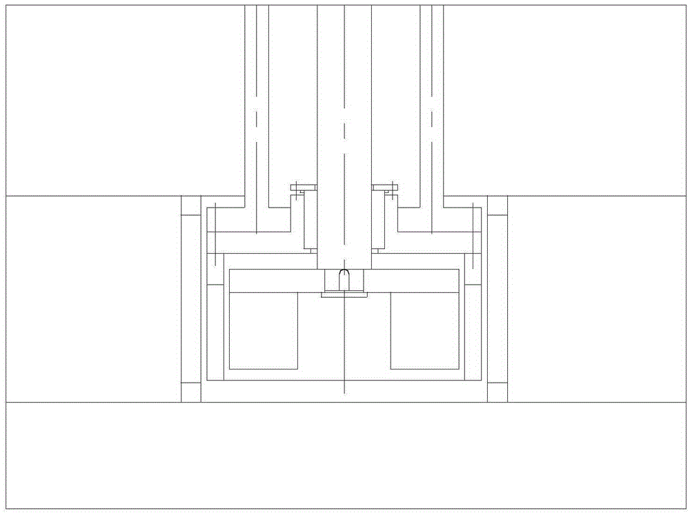
The invention provides a high-efficiency and high-shearing emulsifying machine. The high-efficiency and high-shearing emulsifying machine comprises a motor, a dual output shaft gearbox, a central stirring paddle, an external stirring paddle and an emulsification tank, wherein the emulsification tank is in a cylindrical structure; a cover plate is arranged at the top of the emulsification tank; the dual output shaft gearbox is arranged on the upper side of the center of the cover plate; the motor is connected to the top end of the dual output shaft gearbox; the dual output shaft gearbox is transmitted by adopting two stages of gears which are internally and externally meshed or planetary gears; a central input shaft and an external output shaft are arranged in the dual output shaft gearbox; the lower ends of the central stirring shaft and the external stirring shaft penetrate through the cover plate and stretch into the emulsification tank; the central stirring paddle is mounted on the central stirring shaft; the external stirring paddle is mounted on the external stirring shaft through a fixed hoop; the lower ends of the central stirring shaft and the external stirring shaft are mounted on a bottom bracket. By adopting a two-rotor emulsification head with relative positive and negative rotation and a plurality layers of stirring paddles with unlimited diameters, the shearing force and the circulation flow are exponentially increased.

Description

technical field [0001] The invention relates to the technical field of emulsification equipment, in particular to a high-shear emulsification machine. Background technique [0002] Emulsifying machine is a common equipment in textile, chemical industry, coating, pharmaceutical, cosmetics and other fields. The equipment generally includes a mixing drum, a motor with the output shaft facing downwards arranged above the mixing drum, a stirring shaft arranged on the output shaft of the motor and coaxially rotating at high speed with the motor, the stirring shaft goes deep into the bottom of the mixing drum, and the bottom end of the stirring shaft is sleeved There is a rotor, and a stator is installed at the bottom of the mixing drum. The wet medium is micronized, homogenized and emulsified under the shear force between the rotor and the stator, and the required finished product with fine particles and uniform liquid is obtained. [0003] However, the current emulsifiers have r...

Claims


Application Information

Patent Timeline
Patent Type & Authority Patents(China)
IPC IPC(8): B01F7/16B01F3/08
Inventor 李宏伟鲍学全梁鸿雁
Owner ANHUI SONGYU ENG TECH EQUIP
Learn More