Method and magnetic resonance apparatus for determining a scan sequence based on a pulse response of the gradient system

Active Publication Date: 2018-05-03
SIEMENS HEALTHCARE GMBH
View PDF3 Cites 2 Cited by
  • Summary
  • Abstract
  • Description
  • Claims
  • Application Information

AI Technical Summary

Benefits of technology

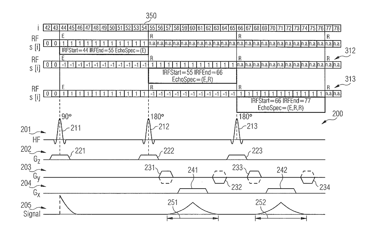
This patent is about a method for determining a scan sequence for magnetic resonance imaging (MRI). The scan sequence is based on a protocol called a scan protocol, which is designed by a user and specifies the desired attributes of the MRI image, such as the type of image to be generated, the resolution, and which parts of the body are to be shown. The MRI machine then uses this information to determine the specific values for the radio-frequency pulses, scan times, and gradient pulses needed to create the desired image. By optimizing these values, the MRI machine can create images that better meet the user's needs. The patent also notes that it may not be necessary to have a continuous reference k-space trajectory (a sequence of data points used to create the image) in all sampling intervals, which can improve the efficiency of the optimization process.

Problems solved by technology

It is frequently observed that the gradient fields designated for use deviate from gradient fields that are actually observed (gradient field errors) when the scan sequence is executed.
For example, the gradient field error can occur as the result of eddy currents and / or mechanical resonances.
Generally, the gradient system of the MR installation has a complicated system response between the specified or programmed gradient pulses and the gradient fields actually produced thereby.
It has been observed that gradient field errors can be particularly significant for certain scan sequences.
For example, significant gradient field errors can occur in scan sequences with non-Cartesian k-space trajectories, for example spiral trajectories or trajectories with radially oriented branches.
Generally, trajectories with rapid changes to the gradient fields can effect significant gradient field errors.
The gradient field error can result in artifacts such as ghosts and / or blurring in the MR images.
The gradient field error may also result in reduced spatial resolution.
This complicates the analysis of physical information in the MR images.
This means that, often, rapid changes to gradient fields cannot be generated or can be generated only to a restricted degree.
This can result in persistent gradient field errors during the emission of RF pulses, which cause inaccuracies in the manipulation of the nuclear spin magnetization.

Method used


Image

  • Method and magnetic resonance apparatus for determining a scan sequence based on a pulse response of the gradient system
  • Method and magnetic resonance apparatus for determining a scan sequence based on a pulse response of the gradient system
  • Method and magnetic resonance apparatus for determining a scan sequence based on a pulse response of the gradient system

Examples


Embodiment Construction

[0049]The above-described properties, features and advantages of this invention and the way in which they are achieved will become clearer and more easily understandable in connection with the following description of the exemplary embodiments, which will be explained in more detail in connection with the drawings.

[0050]The following describes the present invention with reference to preferred embodiments and with reference to the drawings. In the figures, the same reference numbers designate the same or similar elements. The figures are schematic presentations of different embodiments of the invention. Elements depicted in the figures are not necessary shown true-to-scale. Instead, the different elements shown in the figures are depicted such that their function and general purposes can be understood by the person skilled in the art. Connections and couplings between functional units and elements depicted in the figures can also be implemented as indirect connections or couplings. A...


PUM


Abstract

In a magnetic resonance installation and a corresponding method, a scan sequence is determined based on a representation in k-space of a pulse response of a gradient system of the magnetic resonance installation.

Description

BACKGROUND OF THE INVENTIONField of the Invention[0001]The present invention concerns a magnetic resonance apparatus and method to determine a scan sequence based on a pulse response of a gradient system of the apparatus, in particular, based on a representation of the pulse response in k-space.Description of the Prior Art[0002]In magnetic resonance imaging, gradient fields are used to spatially encode the magnetic resonance (MR) signals that are entered into a memory organized as k-space. Spatially resolved MR images can be obtained therefrom.[0003]The accuracy of the spatial resolution of the MR images is correlated with the accuracy with which the gradient fields that are used is known. It is frequently observed that the gradient fields designated for use deviate from gradient fields that are actually observed (gradient field errors) when the scan sequence is executed. For example, the gradient field error can occur as the result of eddy currents and / or mechanical resonances. Gen...

Claims


Application Information

Patent Timeline
IPC IPC(8): G01R33/48G01R33/58G01R33/385
CPCG01R33/4818G01R33/583G01R33/385G01R33/5616G01R33/56518G01R33/56572
Inventor KLUGE, THOMAS
Owner SIEMENS HEALTHCARE GMBH
Why Eureka
Try Eureka