
Pressure control device for a liquid

a control device and liquid technology, applied in the direction of fluid pressure control, process and machine control, instruments, etc., can solve the problems of non-negligible deviations, change of axial position, and relatively fragile seat, so as to achieve high efficiency and cost-effective

Active Publication Date: 2018-05-03
KOMET AUSTRIA GMBH
View PDF9 Cites 5 Cited by
  • Summary
  • Abstract
  • Description
  • Claims
  • Application Information

AI Technical Summary

Benefits of technology

The present invention aims to provide a pressure control device for a liquid that is highly efficient, cost-effective, easy to manufacture and assemble, and can be easily inspected once installed. The technical effects include reduced costs, improved efficiency, and ease of manufacture and assembly.

Problems solved by technology

A first drawback of this arrangement is that the pressure of the fluid that comes out of this device may be affected by non-negligible deviations from the desired value during operation of the system.
This is because the provision of a single support strut imparts a given elasticity to the seat, that can lead to a change of its axial position when the fluid in the supply circuit generates water hammers or when foreign matters such as grass, leaves, stones or the like.
Nevertheless, in addition to being flexible, the seat is also relatively fragile because it may be broken or damaged if a great stress is transferred thereupon.
A further drawback of this solution is that this seat is rigidly joined to an annular support that is distinct and separate from the enclosure of the device, which makes the assembly of the latter relatively complex, due to the great number of its parts.
Furthermore, this configuration increases both the manufacturing costs and the assembly time for the device.
Also, another drawback of this arrangement is that this device requires great care during inspection, as external pointed tools are used therefor, which may damage the seat.
Furthermore, in order to remove impurities such as grass, soil or the like, which build up at the seat during operation of the system, the device is often washed with an abrasive liquid, that might cause wear of the seat, thereby causing an undesired change of liquid delivery pressure.

Method used


Image

  • Pressure control device for a liquid
  • Pressure control device for a liquid
  • Pressure control device for a liquid

Examples


Embodiment Construction

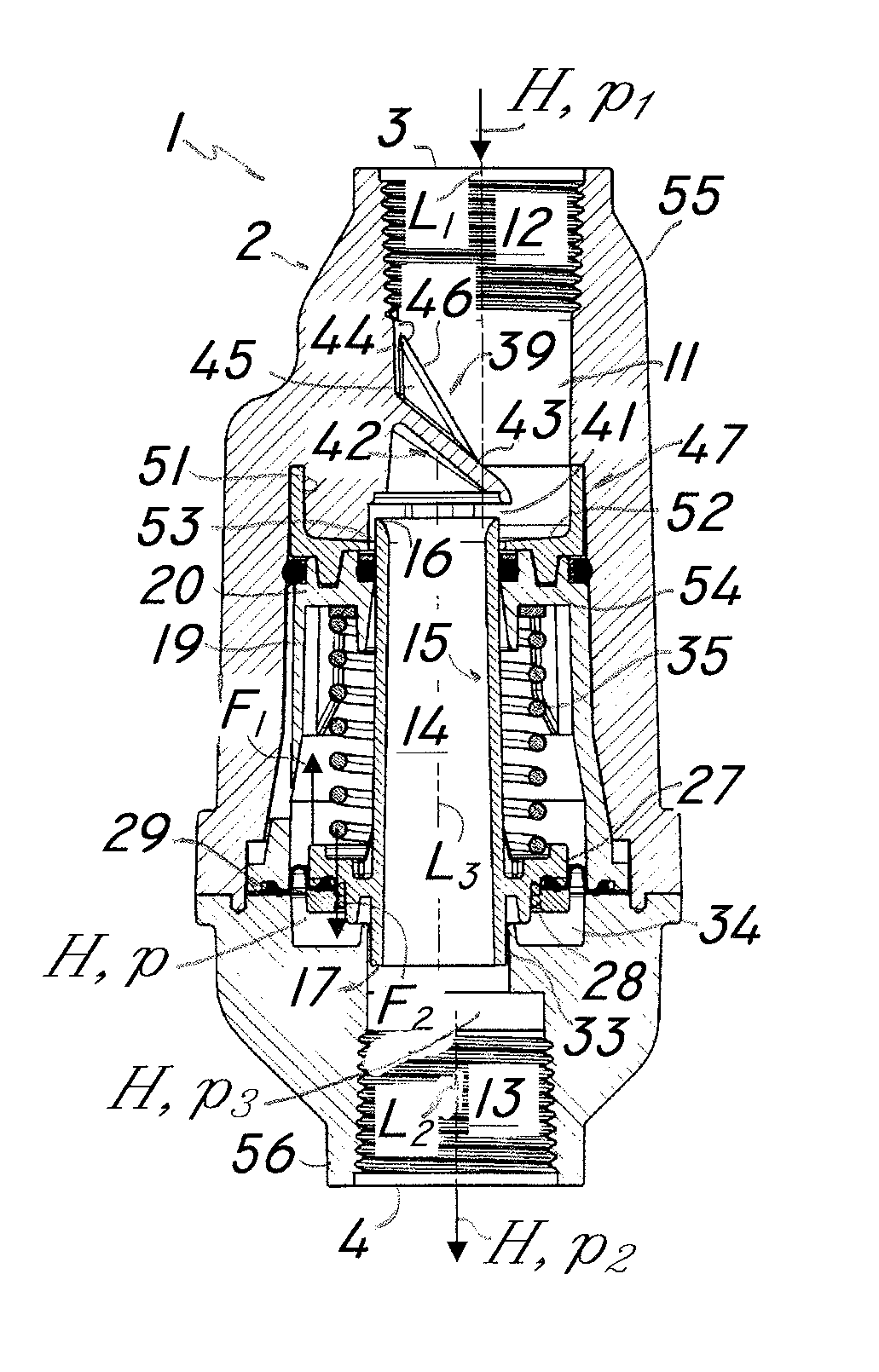
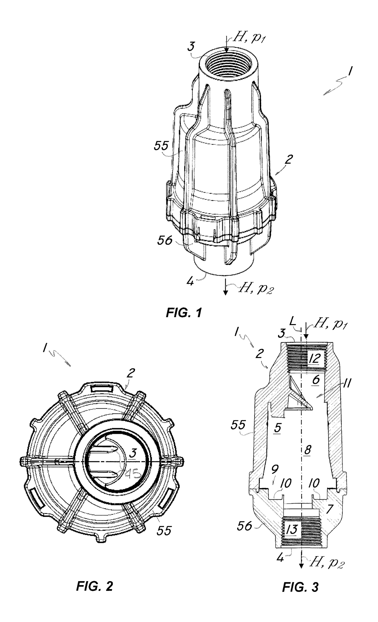
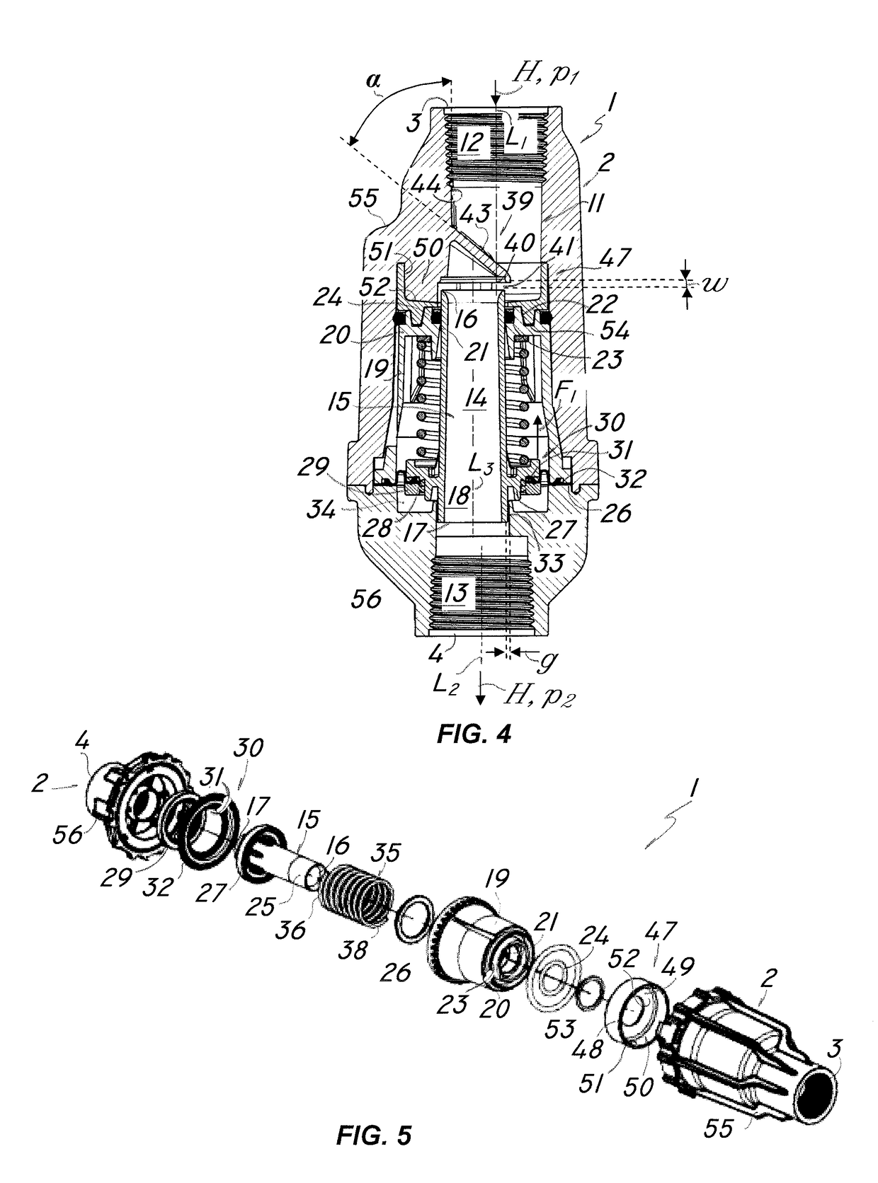
[0036]Particularly referring to the figures, numeral 1 shows and designates a regulator device for regulating the pressure of a liquid H, e.g. water, that comes from a supply line A.

[0037]As a non limiting example, the regulator device 1 may be installed in irrigation systems for uniform distribution of the liquid H on a predetermined area to be irrigated or cooled, not shown.

[0038]The control device 1 may be installed upstream from the sprinklers, not shown, for the jet of liquid H to be delivered at a substantially constant pressure, substantially irrespective of the size of the delivery nozzle that is mounted to the sprinkler.

[0039]The pressure regulator device 1 of the invention comprises a main hollow body 2 having an inlet end 3 and an outlet end 4 for the liquid, and designed to be connected with the former to a supply line for the liquid H and with the latter to a sprinkler, both not shown.

[0040]In the illustrated embodiment, the main body 2 has a substantially tubular shape...


PUM


Abstract

A pressure regulating device for a liquid includes a main hollow body having an inlet end and an outlet end for the liquid, which are connected via a longitudinal passage, a tubular valve member, which is slidingly accommodated in the passage and has a regulating end upstream from the flow of the liquid, a seat placed inside the passage, upstream from the valve member, and having a transverse surface formed in the passage to interact with the regulating end of the valve member and define therewith a part having an adjustable width for the liquid. The seat is eccentrically supported in the passage and is formed of one piece with the main body, and is supported proximate to the inlet end for the liquid by a pair of longitudinal support wings substantially parallel to the flow direction.

Description

FIELD OF THE INVENTION[0001]The present invention generally finds application in the field of irrigation systems for agricultural and industrial applications, and a pressure control device for a liquid, particularly designed to be installed in irrigation systems or the like.BACKGROUND ART[0002]Agricultural and / or industrial irrigation systems are known in the art, which comprise a line for supplying an irrigation liquid, e.g. water, connected to a plurality of sprinkler devices for distributing a jet of such liquid to a soil portion to be irrigated.[0003]A peculiar characteristic of these systems is that they distribute a constant amount of liquid to a given soil portion, to irrigate it in a substantially uniform manner.[0004]Furthermore, the sprinkler devices may be either stationary, to always irrigate the same soil portion, or movable relative to the supply conduit for substantially constant-speed sweeping of a given cultivated surface.[0005]Almost all the sprinklers for use in i...

Claims


Application Information

Patent Timeline
IPC IPC(8): G05D16/06F16K1/12
CPCG05D16/0608G05D16/0636F16K1/126F16K1/42
Inventor DRECHSEL
Owner KOMET AUSTRIA GMBH
Learn More