Method of autonomous lane identification for a multilane vehicle roadway

a multi-lane vehicle and autonomous technology, applied in the field of roadway lane management, can solve the problems of reducing the capacity of tolling vehicles, the potential cost of a system to detect these users and charge for use, and the critical concern of expense, so as to improve the charging performance and improve the autonomous lane identification

Active Publication Date: 2018-05-03
APPLIED TELEMETRICS HLDG INC
View PDF4 Cites 14 Cited by
  • Summary
  • Abstract
  • Description
  • Claims
  • Application Information

AI Technical Summary

Benefits of technology

[0023]The present method and system are directed at honing the geographic location of a vehicle to enable an in-vehicle, lane-identification system for lane-use management purposes, including charging for lane use. The method and system aim to improve charging performance by addressing certain radio-signal based positioning errors which may occur for any positioning technology such as GNSS, Cell-tower or WiFi or equivalent, particularly within urban environments or other forms of harsh signal terrain that is antithetical to reliable location determination using radio technologies. The method and system presented here will also improve autonomous lane identification on open highways, where “autonomous” means “without the use of roadside equipment or infrastructure”.

Problems solved by technology

A key issue for HOT lanes is the potential expense of a system to detect these users and to charge for use.
That means reduced capacity to accommodate tolled vehicles compared to a lane in which every vehicle is being tolled.
A critical concern is expense.
Using systems that require cameras, RFID readers, infrared sensors, or other similar sensing and detection systems requires expensive roadside infrastructure, such as hardened equipment mounted on gantries requiring power and maintenance.
Beyond GNSS, this solution requires additional equipment, complex processing and sometimes a manual examination and intervention.
In many circumstances, this solution can be negatively influenced by several GNSS and vehicle-travel error sources, described below under the subject of Lane Drift.
Unfortunately, positioning errors ranging up to a few tens of meters are common in automotive telemetry systems that use wireless radio-signal based positioning systems.
Such systems can lead to lane uncertainty resulting in mischarging.
It is generally not possible to know whether such temporary excursions are from intentional or unintentional causes.

Method used


Image

  • Method of autonomous lane identification for a multilane vehicle roadway
  • Method of autonomous lane identification for a multilane vehicle roadway
  • Method of autonomous lane identification for a multilane vehicle roadway

Examples


Embodiment Construction

[0064]When using telemetric location methods such as GNSS, cell-tower or WiFi or equivalent, particularly within urban environments or other forms of harsh signal terrain, it is well known that errors of a few or several meters are common. These errors are often mitigated with application-specific equipment or application specific processing for specific contexts.

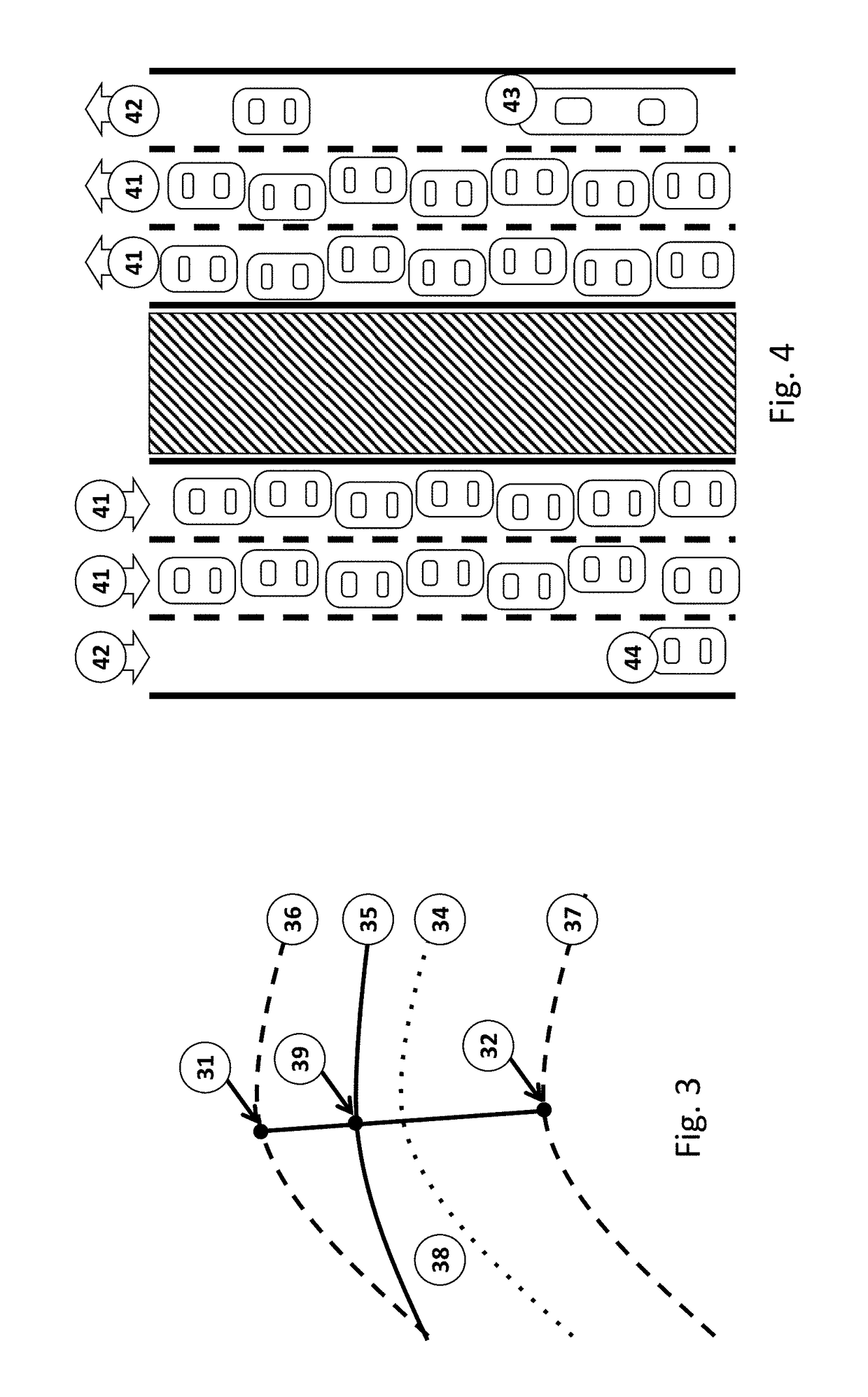
[0065]In the case of this invention—lane identification within a multilane vehicle roadway—vehicles may be segregated by type (bus, truck, hazardous goods, car), occupancy (single occupant, multi-occupant), or by usage fee (toll or no toll) or other combination or distinction. FIG. 4 shows an instance of this for free lanes 41 versus high occupancy / toll lanes 42. This invention is useful for high occupancy / toll (“HOT”) contexts, but it is not restricted to tolling applications. On the contrary, it can be applied in other traffic, travel and infrastructure management applications that rely on detecting lane of travel.

[0066]T...


PUM


Abstract

A method is provided for identifying whether a vehicle has entered, departed, or stayed in a target lane as opposed to an adjacent non-target lane of a segmented roadway. Signals are received from at least one signal source at a receiver within, attached to or integrated into the vehicle marking the geographic position of the vehicle at a sampling rate in a detailed travel path. At each sampled point in the travel path, the method compares the standard perpendicular distance between:the vehicle and the target lane centerline (d1); andthe vehicle and the non-target lane centerline (d2);It is assessed that the vehicle is in the target lane if the distance d1 is less than the distance d2, and otherwise, it is assessed that the vehicle is in the non-target lane. From a time (t1) at which the vehicle is assessed to be departing from the target lane, each such sampled point is deemed to be an excursion point and the excursion point departure distances are summed until the vehicle is assessed to return to the target lane, or the detailed travel path ends, at a time (t2); andif:the sum of the excursion point departure distances is less than a threshold distance, orthe time from t1 to t2 is less than a threshold time,the vehicle is treated as having remained in the target lane, and otherwise, the vehicle is treated as having changed to the non-target lane between time t1 and t2. A related system is also provided.

Description

CROSS-REFERENCE TO RELATED APPLICATIONS[0001]This application is a continuation-in-part of co-pending U.S. patent application Ser. No. 14 / 598,038, filed Jan. 15, 2015, which is herein incorporated by reference.BACKGROUNDField[0002]The invention relates to roadway lane management, vehicle segregation by lane-use, charging methods and systems for vehicle tolling, and optimization of the charging performance of electronic tolling for a specific lane of travel.Description of the Related Art[0003]For managing flow in traffic lanes, sometimes it is useful or desired to toll some traffic lanes, but not all. An example of this is to toll only a single lane on a multi-lane highway. Another example might be to toll several or all of the lanes, but at different rates. A third potential would be to permit the use of a bus lane by a private vehicle subject to a toll. A fourth potential is to segregate, count, or direct vehicles in lanes by vehicle type or other measure.[0004]A well-known example...

Claims


Application Information

Patent Timeline
Patent Type & Authority Applications(United States)
IPC IPC(8): G07B15/06G01C21/34G01C21/36G08G1/01
CPCG07B15/06G01C21/3407G01C21/3453G01C21/3626G08G1/0112G06Q50/30G08G1/012G08G1/0129H04W4/021H04W4/027H04W4/029H04W4/40G06Q40/00H04W84/00G06V20/53G06V20/588
Inventor GRUSH, BERNARDD'HOLLANDER, ROGERLEBLANC, JOSEPH
Owner APPLIED TELEMETRICS HLDG INC
Why Eureka
Try Eureka