Load sharing between parallel connected power converters

a power converter and parallel connection technology, applied in the direction of power conversion systems, dc-dc conversion, dc source parallel operation, etc., can solve the problems of degrading the output voltage regulation, inaccurate load current sharing, and excessive sag of the output voltage, so as to achieve high-regulated output voltage, good load sharing transient response, and control output current very effectively

Active Publication Date: 2018-05-03
TT ELECTRONICS POWER SOLUTIONS US INC
View PDF2 Cites 4 Cited by
  • Summary
  • Abstract
  • Description
  • Claims
  • Application Information

AI Technical Summary

Benefits of technology

[0007]In some implementations, one or more of the following advantages are present.
[0008]For example, in a typical implementation, the system disclosed herein advantageously is able to maintain a highly regulated output voltage, particularly in the presence of transients in line voltage or load current. Moreover, the system is generally able to control the output current very effectively from each respective one of the power converters in the system so that they share the total load current equally. The system has a very good load sharing transient response, particularly as compared to prior art parallel-connected power converter systems. Moreover, in some implementations, particularly where there is a designated secondary or backup master converter, the system has built-in redundancy, so that failure of a primary master power converter, for example, or perhaps any one of the other parallel-connected power converters, can be tolerated as long as there is sufficient current capacity available from the remaining power converters in the system. Moreover, in a typical implementation, effective load sharing can be achieved among the multiple parallel connected power converters without needing a separate control system that is external to the power converters.

Problems solved by technology

In some instances, this lower bandwidth may not allow for accurate current sharing during load transients, which may cause one or more of the power converters to go into a current limiting state, for example, resulting in excessive sag of the output voltage.
The no-load output voltages may drift with time and temperature, resulting in inaccurate load current sharing.
Also, the droop characteristics may tend to degrade the output voltage regulation.

Method used


Image

  • Load sharing between parallel connected power converters
  • Load sharing between parallel connected power converters
  • Load sharing between parallel connected power converters

Examples


Embodiment Construction

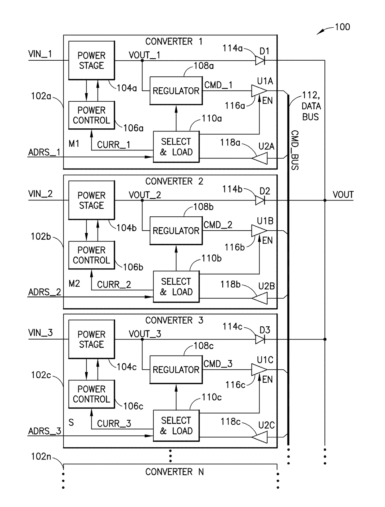
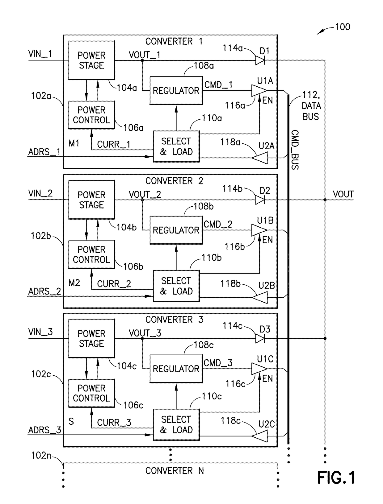
[0017]FIG. 1 is schematic diagram showing an exemplary power supply system 100 with multiple power converters 102a, 102b, 102c, . . . 102n, each of which is generally configured to convert electric energy from one form to another.

[0018]In the illustrated implementation, each power converter 102a, 102b, 102c, . . . 102n has a main input (where it receives an input voltage VIN_1, VIN_2, VIN_3, . . . VIN_n), and a main output (to which it outputs an output voltage VOUT_1, VOUT_2, VOUT_3, . . . VOUT_n). The main outputs of the parallel power converters in the illustrated implementation are connected together in parallel through isolation diodes 114a, 114b, 114c, . . . 114n to produce a single system output voltage VOUT.

[0019]Each power converter 102a, 102b, 102c, . . . 102n in the illustrated implementation has a buffered command output and a buffered command input. A shared command bus 112 (CMD_BUS) is connected to the buffered command output and the buffered command input for every on...


PUM


Abstract

A power supply system includes multiple power converters, each having an input and an output. The outputs of the power converters are connected together in parallel to produce a single system output. There is a shared command bus that is coupled to each one of the power converters. A control loop in (associated with) a designated one of the power converters is operable to generate a current command signal to be output onto the shared command bus. All of the parallel connected power converters in the power supply system are configured to receive the current command signal from the shared command bus and to adjust an amount of electrical current being supplied by that power converter in response to the current command signal.

Description

FIELD OF THE INVENTION[0001]This disclosure relates to parallel connected power converters and, more particularly, relates to load sharing between parallel connected power converters.BACKGROUND[0002]Certain control systems / techniques for connected power converters (e.g., ones based on single wire current share technology) may use an auxiliary control loop having a bandwidth lower than a main voltage regulation loop to force load sharing. In some instances, this lower bandwidth may not allow for accurate current sharing during load transients, which may cause one or more of the power converters to go into a current limiting state, for example, resulting in excessive sag of the output voltage.[0003]Other control systems systems / techniques for connected power converters (e.g., ones based on droop current sharing technology) may rely on each power converter having a finite output resistance to force current sharing. Accuracy of current sharing in such instances may rely on the no-load o...

Claims


Application Information

Patent Timeline
Patent Type & Authority Applications(United States)
IPC IPC(8): H02M3/156
CPCH02M3/156H02M3/1584H02M3/285H02J1/10
Inventor SYMONDS, NEIL
Owner TT ELECTRONICS POWER SOLUTIONS US INC
Why Eureka
Try Eureka