Lidar scanner with optical amplification

Inactive Publication Date: 2018-05-10
UATC LLC
View PDF8 Cites 8 Cited by
  • Summary
  • Abstract
  • Description
  • Claims
  • Application Information

AI Technical Summary

Benefits of technology

The patent text describes a way to measure the strength of a pulse of light using a photodiode. This can be done using various electronic techniques, such as converting the current through the photodiode into a voltage signal. The strength of the pulse can be used to control bias voltages applied to the photodiode. The patent uses the phrase "pulse strength measurement" to refer to this process. The technical effect of the patent is to enable more accurate control of the output of a photodiode by measuring and analyzing the strength of the current pulse.

Problems solved by technology

Historically to collect accurate distance and reflectance measurements one used photogrammetry techniques, but the process for extracting information from stereo imagery is time consuming, expensive, and unreliable in certain circumstances.

Method used


Image

  • Lidar scanner with optical amplification
  • Lidar scanner with optical amplification
  • Lidar scanner with optical amplification

Examples


Embodiment Construction

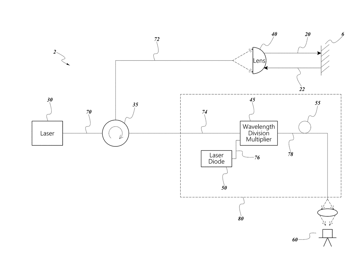
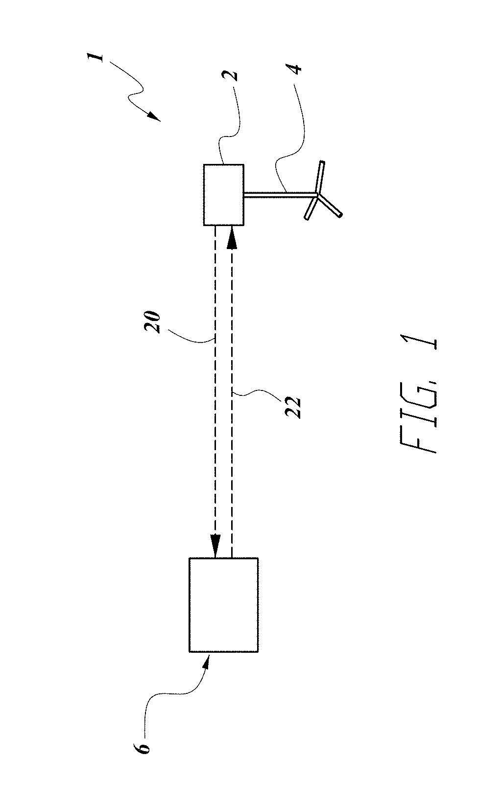
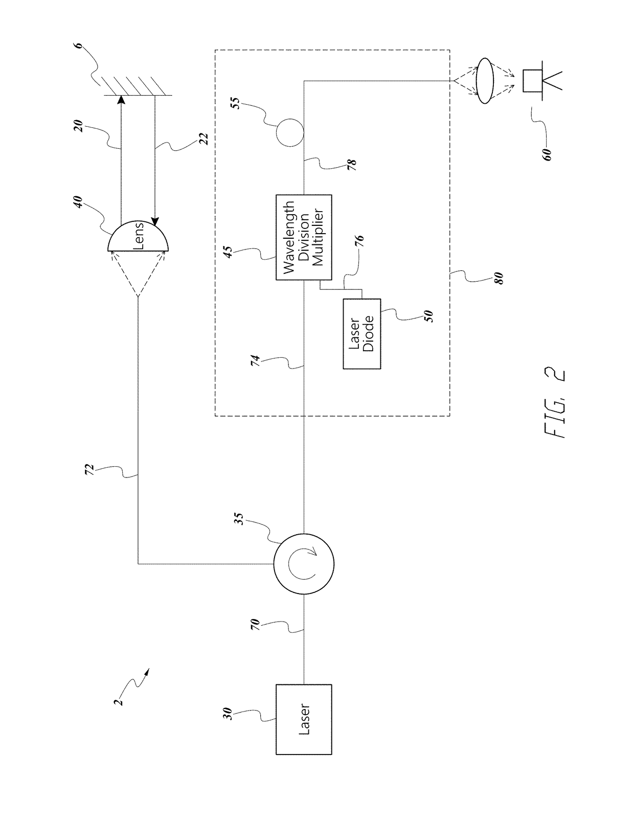
[0015]FIG. 1 depicts an embodiment position sensing device 1. The position sensing device is shown in an arbitrary environment including an object 6. It will be understood that the position sensing device 1 can be used in a variety of environments such as a construction site, a mine, a laboratory, on an autonomous vehicle, or other indoor and outdoor environments. The position sensing device 1 can be configured to measure at least one point, or further at least one spatial map of a portion of the environment, such as the object 6. For example, in the context of an autonomous vehicle, the object 6 measured by the position sensing device 1 can be the road or one or more cars on the road. In some embodiments the position sensing device 1 can measure a particular set of separate and discrete points, whereas in further embodiments the position sensing device 1 can measure a continuous span of points, as will be described further below. The measurement can be made using a brief electromag...


PUM


Abstract

A LiDAR sensor can be provided having a laser, optical circulator, amplifying section, photosensor, and an electronic circuit. The laser can be configured to emit a brief electromagnetic pulse. The optical circulator can be positioned to receive the brief electromagnetic pulse from the laser and direct the brief electromagnetic pulse on an optical path towards an object. The optical circulator can also be configured to receive a reflected pulse from the object caused by the brief electromagnetic pulse. The amplifying section can be positioned to receive the reflected pulse from the optical circulator and be configured to optically amplify the reflected pulse to create an amplified reflected pulse. The photosensor can be positioned to receive the amplified reflected pulse from the amplifying section, and to produce a signal in response to the amplified reflected pulse. Finally, the electronic circuit can be configured to determine an intensity of the reflected pulse and a distance to the object based on a time-of-flight of the electromagnetic pulses.

Description

BACKGROUNDField[0001]The present application relates to optical sensors, and particularly to LiDAR (Light Distance And Ranging) sensors and related devices with optical amplification.Description of the Related Art[0002]The process for measuring distance and reflectance values for objects within an environment without touching those objects is of great interest to many industries including autonomous vehicles, surveying, architecture, entertainment (character generated effects for movies and video games), construction, forensic, and geography applications. Historically to collect accurate distance and reflectance measurements one used photogrammetry techniques, but the process for extracting information from stereo imagery is time consuming, expensive, and unreliable in certain circumstances. Advances in Light Detecting and Ranging (LiDAR) technology have enabled practitioners to scan large area surfaces while collecting billions of data points, each with a precise distance and angle...

Claims


Application Information

Patent Timeline
IPC IPC(8): G01S7/481G01S7/484G01S17/06
CPCG01S7/4816G01S17/06G01S7/484G01S7/4813G01S7/4812G01S7/4818G01S17/10
Inventor HASLIM, JAMES A.
Owner UATC LLC
Why Eureka
Try Eureka