Power supply system control device and power supply system control method

a power supply system and control device technology, applied in the direction of machines/engines, engine starters, transportation and packaging, etc., can solve the problem of delay in an increase in the voltage supplied to the electric load

Active Publication Date: 2018-05-17
NISSAN MOTOR CO LTD
View PDF4 Cites 4 Cited by
  • Summary
  • Abstract
  • Description
  • Claims
  • Application Information

AI Technical Summary

Benefits of technology

[0004]One or more embodiments of the present invention provides a control device and a control method that can supply electric power without delay in response to an increase in the voltage required by electric loads.

Problems solved by technology

This causes a delay in an increase in the voltage supplied to the electric loads.

Method used


Image

  • Power supply system control device and power supply system control method
  • Power supply system control device and power supply system control method
  • Power supply system control device and power supply system control method

Examples


first embodiment

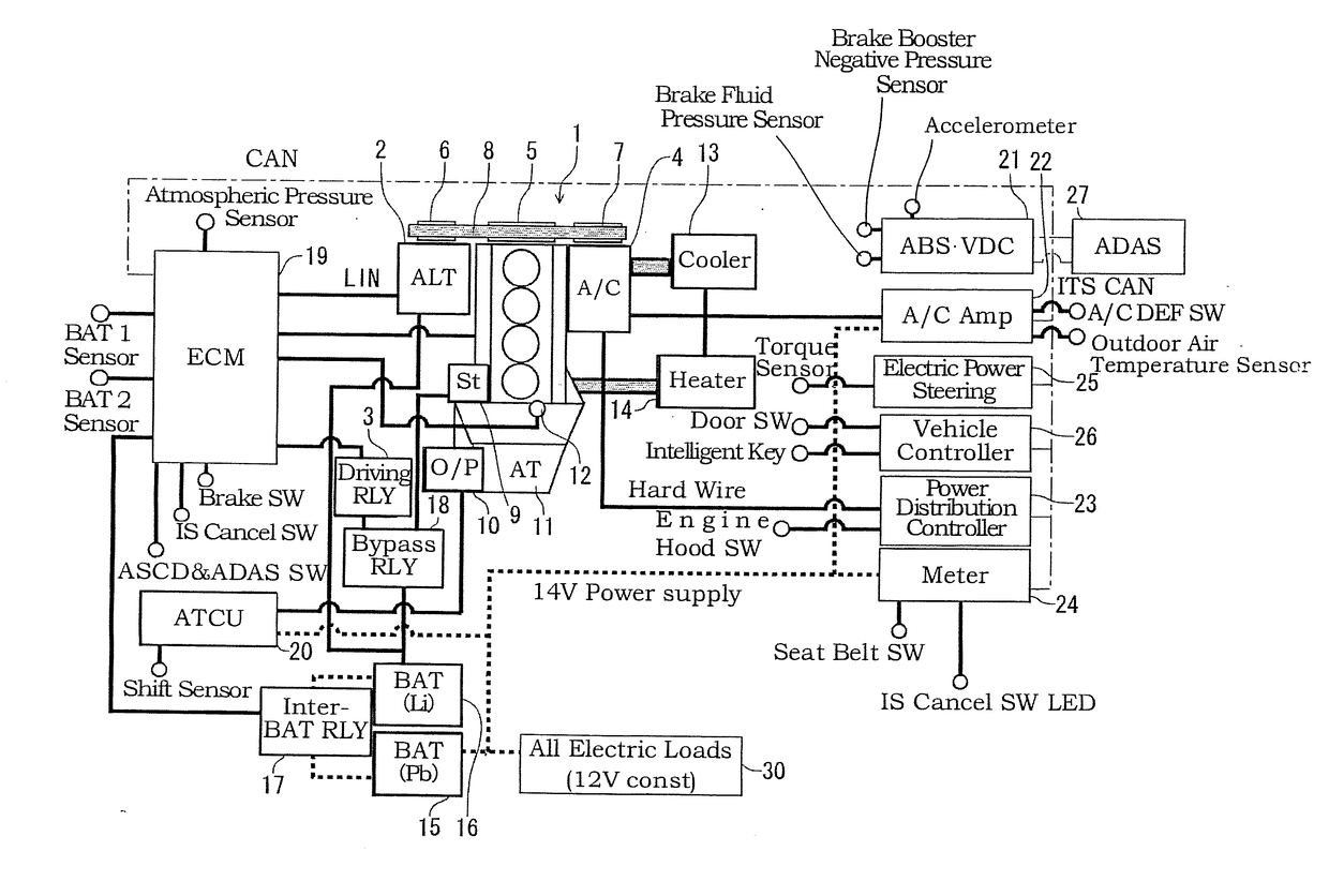
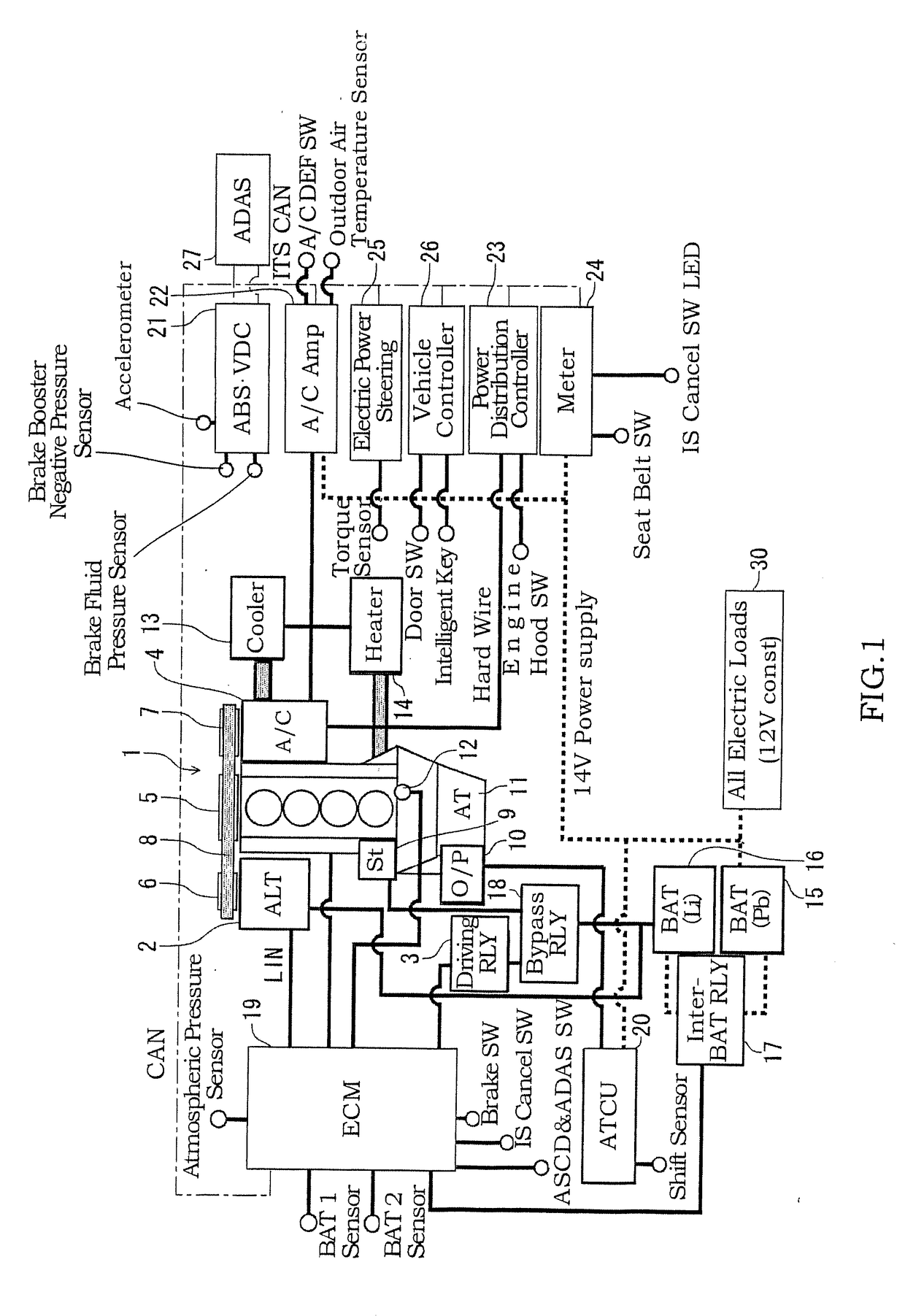
[0019]FIG. 1 is a schematic diagram of a system of an engine having an idling stop function according to one or more embodiments of the present invention.

[0020]As shown in FIG. 1, in an engine 1, an electric generator 2 and an air conditioner compressor 4 are provided respectively at one side and the other side, each via a non-illustrated bracket and the like. A belt 8 is wound across a crank pulley 5 mounted on a distal end of a crankshaft of the engine 1, an electric generator pulley 6 mounted on a distal end of a rotation shaft of the electric generator 2, and a compressor pulley 7 mounted on a distal end of a rotation shaft of the air conditioner compressor 4. Thus, the crank pulley 5, the electric generator pulley 6, and the compressor pulley 7 are mechanically joined to one another.

[0021]Although the three pulleys, i.e., the crank pulley 5, the electric generator pulley 6, and the compressor pulley 7 are mechanically joined to one another using one belt 8 in FIG. 1, each of th...

second embodiment

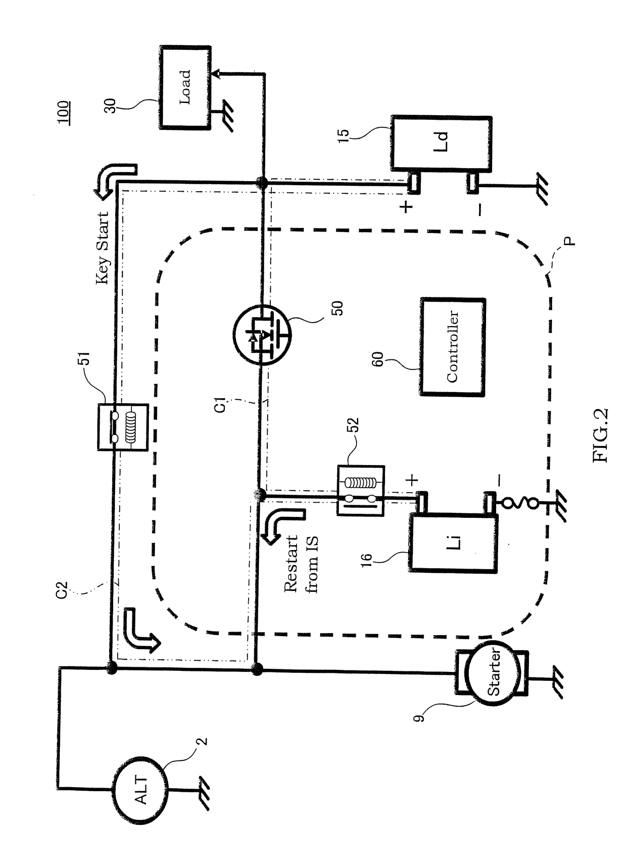
[0113]FIG. 10 illustrates a power supply system with a third configuration (hereinafter also referred to as a type-3 power supply system) 100″. Note that the elements similar to the elements shown in FIG. 2 are given the same reference signs thereas.

[0114]FIG. 10 differs from FIG. 2 in that a MOSFET 71, which includes a parasitic diode whose forward direction is opposite to the forward direction of the parasitic diode of the MOSFET 50, is connected in series to the MOSFET 50, and in that the lithium-ion secondary battery adjunct relay 52 is interposed between the lithium-ion secondary battery 16 and the starter 9, rather than between the MOSFET 71 and the lithium-ion secondary battery 16.

[0115]With the foregoing configuration, should the lithium-ion secondary battery adjunct relay 52 become no longer actuated while remaining in an open state, electric power can be supplied from the lithium-ion secondary battery 16 to all electric loads 30 by controlling the MOSFET 50 and the MOSFET ...


PUM


Abstract

A power supply system control device for controlling a power supply system including an electric generator, a first electricity storage configured to be charged with and to discharge electric power generated by the electric generator, a second electricity storage configured to be charged with and to discharge the generated electric power, two paths connecting between the first electricity storage and the second electricity storage, a switching unit including a first switch configured to switch between a conductive state and a non-conductive state of one of the paths, and a second switch configured to switch between a conductive state and a non-conductive state of the other of the paths, and an electric load of a vehicle that is connected to the first electricity storage side of the switching unit.

Description

BACKGROUNDTechnical Field[0001]The present invention relates to control of a power supply system of a vehicle including two secondary batteries.Related Art[0002]There is a known vehicular power supply system that includes a lithium-ion battery and a lead battery as two secondary batteries. JP 5494498B describes, as control of such a power supply system, voltage-variable control in which the voltage (set voltage) of electric power output from an electric generator is variably controlled. Furthermore, according to the description of this document, when electric loads (e.g., headlights and windshield wipers) that require high voltage have been actuated, the voltage-variable control is prohibited by fixing the set voltage between a voltage upper limit and a voltage lower limit of the voltage-variable control, or control for reducing an upper limit of the set voltage and increasing a lower limit of the set voltage is performed in the voltage-variable control.SUMMARY OF INVENTION[0003]The...

Claims


Application Information

Patent Timeline
Patent Type & Authority Applications(United States)
IPC IPC(8): B60R16/033B60R16/00H02J7/14
CPCB60R16/033B60R16/005H02J7/1423B60R16/04B60R16/03H02J7/1446F02N11/006F02N11/04F02N11/0833F02N11/084F02N11/0866F02N2200/0813H02J2310/46Y02T10/40H02J7/14F02N11/0837Y02T10/92
Inventor TAHARA, MASAHIKOTSUCHIYA, TERUMASATEZUKA, ATSUSHIKOIKE, TOMOYUKIWATANABE, MUNEMITSUKOISHI, AKIFUMI
Owner NISSAN MOTOR CO LTD
Why Eureka
Try Eureka