Safety improvements for UV radiation in aquatic applications

a technology for uv radiation and aquatic applications, applied in the direction of disinfection, transportation and packaging, vessel construction, etc., can solve the problems of clogging water inlets, affecting the safety of aquatic aquatic applications, and causing substantial problems such as biofouling

Active Publication Date: 2018-05-17
KONINKLJIJKE PHILIPS NV
View PDF0 Cites 6 Cited by
  • Summary
  • Abstract
  • Description
  • Claims
  • Application Information

AI Technical Summary

Benefits of technology

[0018]Ultraviolet (UV) is that part of electromagnetic light bounded by the lower wavelength extreme of the visible spectrum and the X-ray radiation band. The spectral range of UV light is, by definition between about 100 and 400 nm (1 nm=10−9 m) and is invisible to human eyes. Using the CIE classification the UV spectrum is subdivided into three bands: UVA (long-wave) from 315 to 400 nm; UVB (medium-wave) from 280 to 315 nm; and UVC (short-wave) from 100 to 280 nm. In reality many photobiologists often speak of skin effects resulting from UV exposure as the weighted effect of wavelength above and below 320 nm, hence offering an alternative definition.
[0019]A strong germicidal effect is provided by the light in the short-wave UVC band. In addition erythema (reddening of the skin) and conjunctivitis (inflammation o

Problems solved by technology

In several circumstances biofouling creates substantial problems.
Machinery stops working, water inlets get clogged, and hulls of ships suffer from increased drag.
Biofouling on the hull of ships causes a severe increase in drag, and thus increased fuel consumption.
It appears that most micro-organisms are killed, rendered inactive or unable to reproduce with sufficient U

Method used


Image

  • Safety improvements for UV radiation in aquatic applications
  • Safety improvements for UV radiation in aquatic applications
  • Safety improvements for UV radiation in aquatic applications

Examples


Embodiment Construction

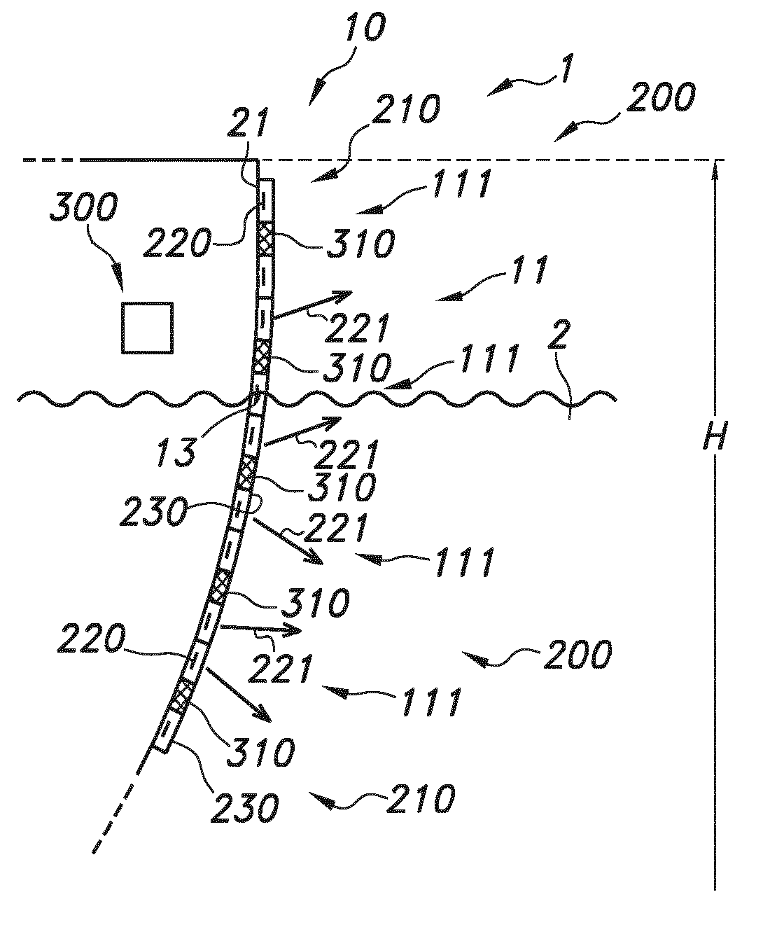
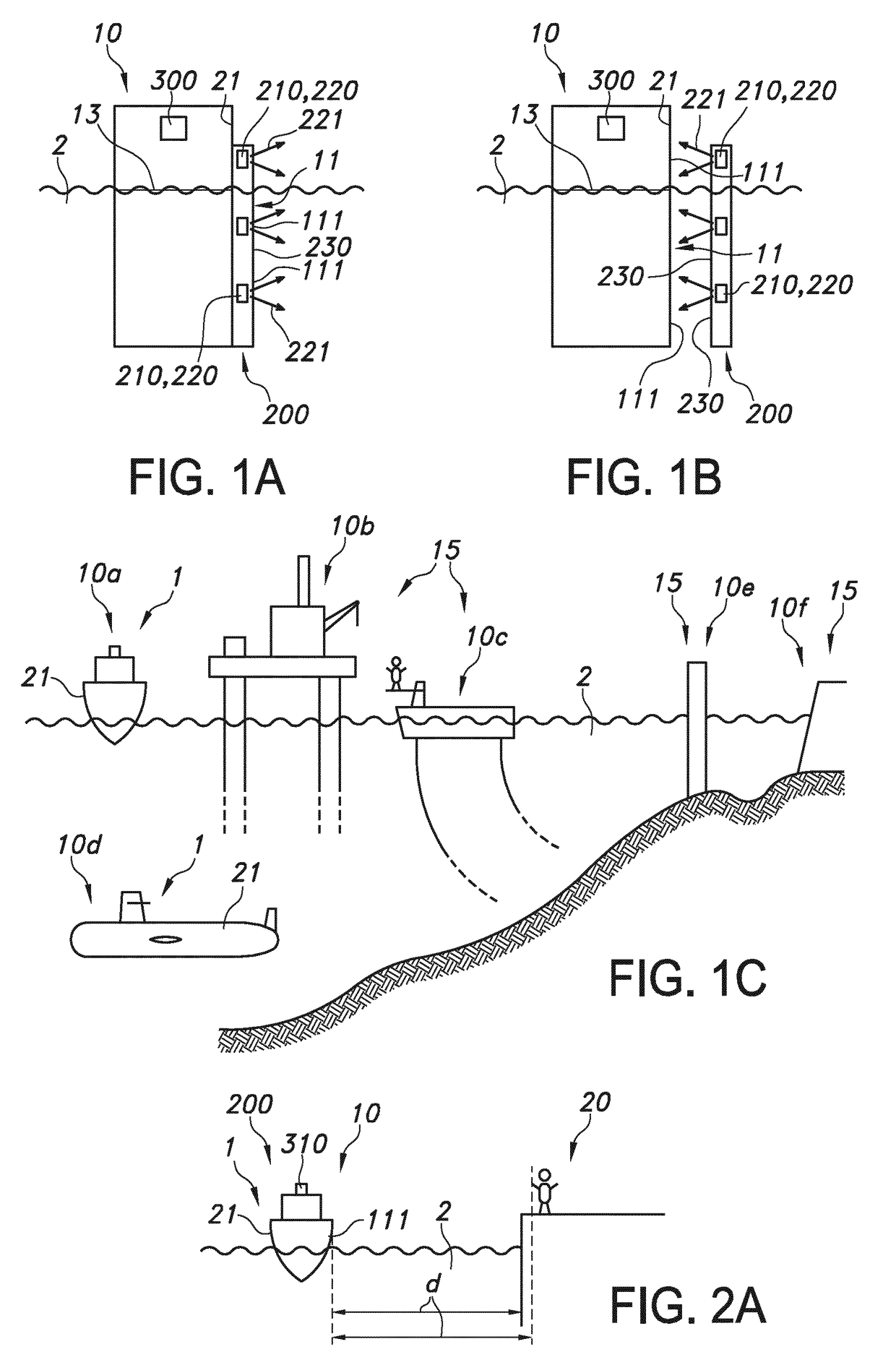
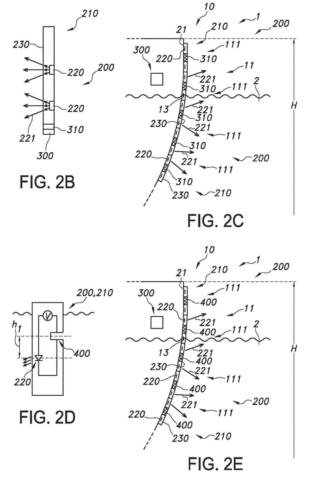
[0079]FIGS. 1a-1b schematically depict embodiments of an object 10 that during use is at least partly submerged in water 2, see the water line 13. The object 10, such as a vessel or a sluice, see also below, further comprises an anti-biofouling system 200 comprising an UV emitting element 210, especially for application of UV radiation 221 to a part 111 of an external surface 11 of the object 10, such as a hull or part or a hull. Here, two embodiments are shown wherein the anti-biofouling system 200, or more especially the UV emitting element 210 is part of an outer surface, and thereby forms in fact part of the outer surface (FIG. 1a) or wherein the UV emitting element 210 is configured to irradiate the outer surface and does not necessarily form part of an outer surface, such as a hull of a ship (FIG. 1b). For instance, the object 10 is selected from the group consisting of a vessel 1 and an infrastructural object 15 (see also below).

[0080]The UV emitting element 210 comprises one...


PUM


Abstract

The invention provides an object (10) that during use is at least partly submerged in water, the object (10) further comprising an anti-biofouling system (200) comprising an UV emitting element (210), wherein the UV emitting element (210) is configured to irradiate with UV radiation (221) during an irradiation stage one or more of (i) a part (111) of an external surface (11) of said object (10) and (ii) water adjacent to said part (111) of said external surface (11), wherein the light source (220) is at least controllable between a first UV radiation level and a second UV radiation level, wherein the first UV radiation level is larger than the second UV radiation level, wherein the object (10) is selected from the group consisting of a vessel (1) and an infrastructural object (15), wherein the object (10) further comprises a control system (300) configured to control said UV 221 radiation (221) as function of input information comprising information of one or more of (i) a location of the object (10), (ii) movement of the object (10), (iii) a distance (d) of the object (10) to a second object (20), and (iv) a position of the part (111) of the external surface (11) relative to the water.

Description

FIELD OF THE INVENTION[0001]The invention relates to an object that during use is at least partly submerged in water, especially a vessel or an infrastructural object.BACKGROUND OF THE INVENTION[0002]Anti-biofouling methods are known in the art. US2013 / 0048877, for instance, describes a system for anti-biofouling a protected surface, comprising an ultraviolet light source configured to generate ultraviolet light, and an optical medium disposed proximate to the protected surface and coupled to receive the ultraviolet light, wherein the optical medium has a thickness direction perpendicular to the protected surface, wherein two orthogonal directions of the optical medium orthogonal to the thickness direction are parallel to the protected surface, wherein the optical medium is configured to provide a propagation path of the ultraviolet light such that the ultraviolet light travels within the optical medium in at least one of the two orthogonal directions orthogonal to the thickness dir...

Claims


Application Information

Patent Timeline
IPC IPC(8): B63B59/04A61L2/10C02F1/32
CPCB63B59/04A61L2/10C02F1/325A61L2202/14C02F2201/326C02F2201/3227C02F2303/20B08B17/02B08B7/0057H05B47/105
Inventor SALTERS, BART ANDREHIETBRINK, ROELANT BOUDEWIJN
Owner KONINKLJIJKE PHILIPS NV
Why Eureka
Try Eureka