Method and device for laser-assisted separation of a portion from a sheet glass element

a technology of sheet glass and laser assisted separation, which is applied in the direction of glass making apparatus, manufacturing tools, welding/soldering/cutting articles, etc., can solve the problems of affecting the quality of glass, so as to achieve efficient and clean separation

Active Publication Date: 2018-05-17
SCHOTT AG
View PDF32 Cites 25 Cited by
  • Summary
  • Abstract
  • Description
  • Claims
  • Application Information

AI Technical Summary

Benefits of technology

[0014]The present invention is therefore based on the object to allow an efficient and clean, especially splinter-free separation of a portion from a sheet glass element along non-rectilinear separation lines in such a manner that both the separated portion and the remaining main part of the glass element are not further damaged.

Problems solved by technology

The energy decreases across the entire glass thickness, so the first plasma spots will have the greatest energy and also produce the greatest damage.
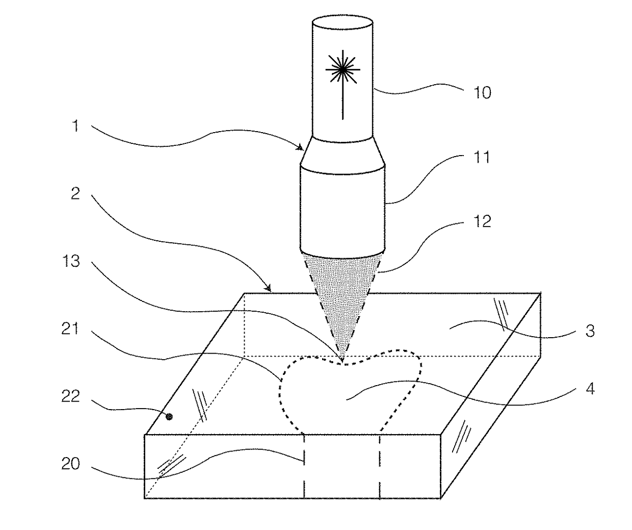
The material is thereby perforated along this separation line and thus pre-damaged.
However, separation will be more difficult if the separation line is curved, has several sections at an angle to one another, or even forms a closed line.
The separation of glass along separation lines that have a generally curved shape, angled sections, or which even define a closed loop is difficult because it is not readily feasible to exert a sufficient bending moment onto the glass along the separation line.
A disadvantage of this method, on the one hand, is its high complexity which reduces economic benefits, and on the other the deterioration of the portion to be separated, which otherwise might be of interest due to its exact fit to the remaining main part of the substrate.
Another disadvantage of the deterioration of the portion are the particles and splinters that are resulting, and therefore elevated cleaning costs.
Both the filament structures per se and additional cracks in the material as caused by a cleaving step are preliminary damages in the material that extends along the separation line.
On the other hand, thermally toughened glass elements are usually not well suited for being cut and severed.
A disadvantage hereof, as mentioned above, is that such glasses cannot be cut very well anymore and will crack more readily than non-toughened or non-tempered glasses, so that the risk of detrimental crack formation will be increased during the contour definition step in this case.
By contrast, with conventional separation methods such as the application of a bending moment, the separation of glass along predetermined breaking lines that have a generally curved shape, angled sections, or even define a closed loop becomes increasingly difficult with increasing thickness of the glass.
This is due to the fact that in the case of conventional separation processes, the risk of jamming between the parts that are still in contact is getting greater and greater with increasing substrate thickness.
Therefore, reliable separation in conventional manner may become difficult or even impossible in case of rather thick glass elements.
However, a disadvantage of this method is that it is only suited for limited glass thicknesses.
Namely, if the glass is too thick, the effect of gap formation due to the yielding of the material is getting weaker relative to an expansion caused by the heating of the contour to be separated in the plane of the substrate.
In case of thicker glass elements it is often no longer possible or at least inappropriate to perform the microperforation across the entire thickness in one processing step or by passing the point of incidence of the laser beam along the separation line in a single pass.
Furthermore, in similar manner, filamentary damages can be generated in the volume of the glass element along a second offset line that is spaced from the first offset line.
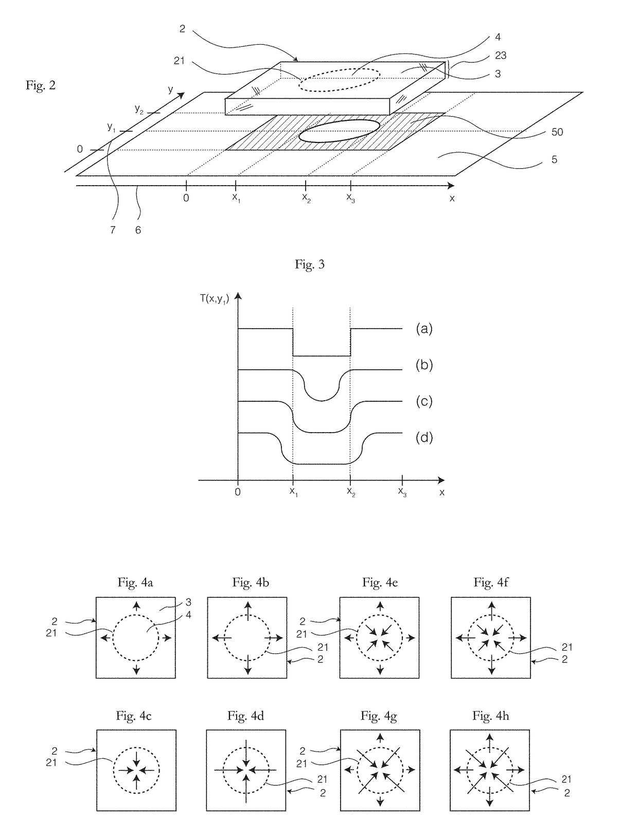
Furthermore, it is also possible to heat the glass element unevenly in the region of the main part, and / or to cool it unevenly in the region of the portion.
The separation of glass along predetermined breaking lines that have a generally curved shape or angled sections using conventional separation methods becomes more and more difficult the more curves or angles the separation line has.
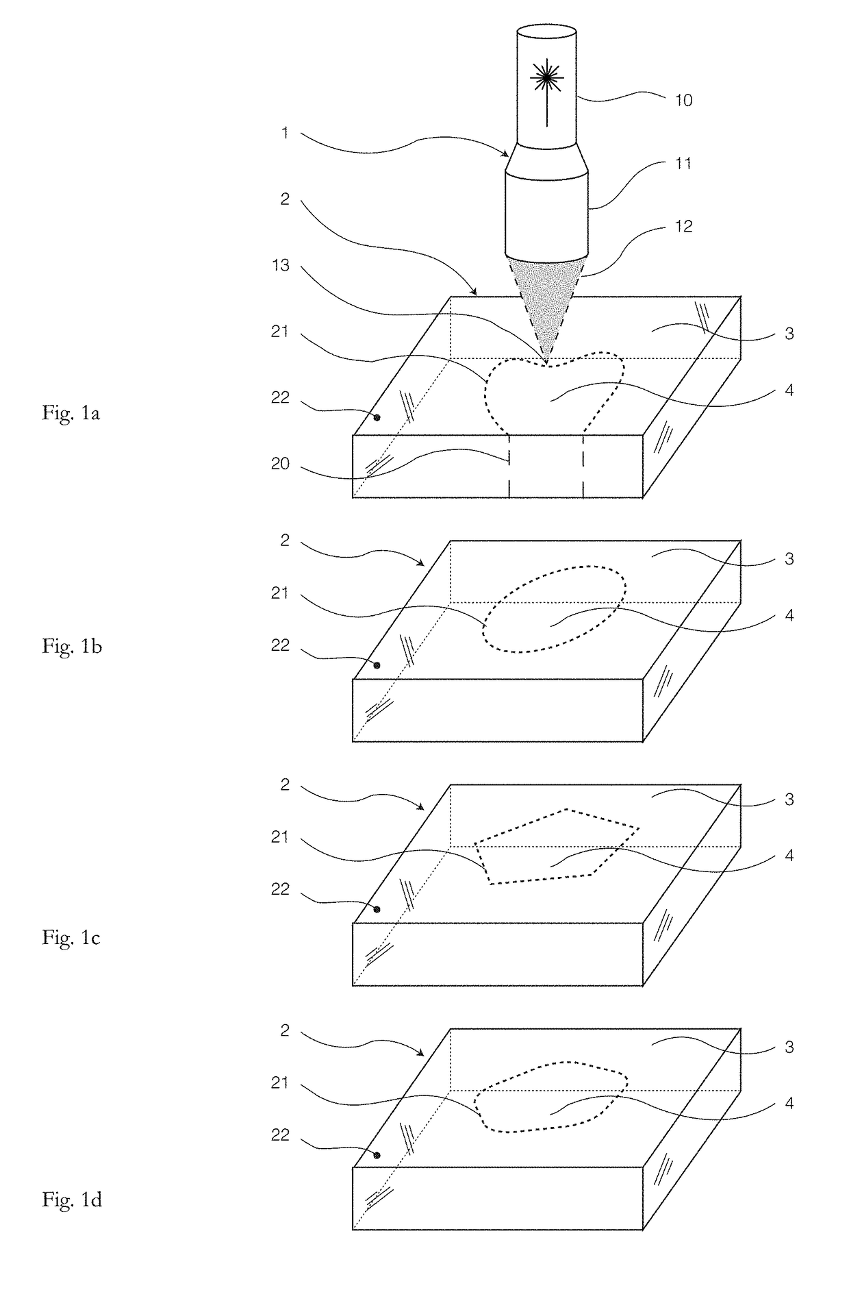
Apart from an inner portion with a closed-loop separation line, the separation of a portion is already particularly difficult if the portion is a partially inner or almost inner portion, so that the separation line is not yet completely closed.
The separation of glass along closed-loop separation lines, that means the separation of an inner portion located within the two-dimensional surface, or in other words the creation of holes or cut-outs in a sheet glass element is difficult for conventional separation methods.
One reason for this, among others, is the aforementioned problem of applying a bending moment, but also that sometimes only few or no material is removed by the laser pulses during the microperforation.
At greater focal depths, that is the more the damage channels are spaced from the entrance side into the glass, it may happen that the lengths of the filamentary damages become shorter.

Method used


Image

  • Method and device for laser-assisted separation of a portion from a sheet glass element
  • Method and device for laser-assisted separation of a portion from a sheet glass element
  • Method and device for laser-assisted separation of a portion from a sheet glass element

Examples


Embodiment Construction

[0103]FIGS. 1a through 1d schematically shows a laser processing device 1, which can be used for microperforating a glass element 2 by introducing filamentary damages 20 along a defined separation line 21 and thus preparing it for subsequent separation.

[0104]Laser processing device 1 comprises an ultrashort pulse laser 10 for directing laser pulses 12 onto the glass element 2. For this purpose, the laser pulses 12 are focused onto the glass element 2 using focusing means 11. The wavelength of the ultrashort pulse laser 10 is selected so that the laser pulses 12 can penetrate into the glass element 2.

[0105]The laser pulses 12 generate a plasma in the volume of the glass element 2 causing the filamentary damages 20. The incidence points 13 of the laser pulses 12 on the glass element 2 are successively displaced over the surface 22 along the defined separation line 21.

[0106]Separation line 21 is defined so that it completely divides the glass element 2 into a portion 4 to be separated ...


PUM

PropertyMeasurementUnit
thicknessaaaaaaaaaa
temperatureaaaaaaaaaa
thicknessaaaaaaaaaa

Abstract

A method for separating a portion from a sheet glass element having a thickness of at least 2 millimeters along an intended separation line that divides the sheet glass element into the portion and a remaining main part is provided. The method includes producing filamentary damages comprising sub-micrometer hollow channels in a volume of the glass sheet element adjacently aligned along the separation line; and heating and/or cooling the glass sheet element to cause expansion and/or contraction so that the portion detaches from the main part along the separation line. The portion and the remaining main part each remain intact as a whole. The step of producing the filamentary damages includes generating a plasma within the volume with laser pulses of an ultrashort pulse laser; and displacing points of incidence of the laser pulses over a surface of the glass sheet element along the separation line.

Description

CROSS REFERENCE TO RELATED APPLICATIONS[0001]This application is a continuation of International Application No. PCT / EP2016 / 066013 filed on Jul. 6, 2016, which claims the benefit under 35 U.S.C. 119(a) of German Application No. 10 2015 111 490.9 filed Jul. 15, 2015, the entire contents of both of which are incorporated herein by reference.BACKGROUND OF THE INVENTION1. Field of the Invention[0002]The invention generally relates to laser-assisted separation of a portion from a sheet glass element. More particularly, the invention relates to laser-assisted separation of a portion from the interior of a sheet glass element.2. Description of Related Art[0003]From WO 2012 / 006736 A2 it is known that irreversible damages in the form of filaments can be caused in a glass substrate by high-energy laser pulses, and that an aligned series of such damages allows to separate the glass. A filament is produced by an ultrashort laser pulse which causes self-focusing to take place inside the glass du...

Claims


Application Information

Patent Timeline
Patent Type & Authority Applications(United States)
IPC IPC(8): C03B33/09C03B33/04B23K26/00B23K26/53
CPCC03B33/091C03B33/04B23K26/0057B23K26/53B23K2203/54C03B33/0222B23K2103/54
Inventor WAGNER, FABIANORTNER, ANDREASSEIDL, ALBRECHTLENTES, FRANK-THOMASGERBAN, JORNSCHMITT, SIMON
Owner SCHOTT AG
Why Eureka
Try Eureka