Spring damper and accelerator device using the spring damper

a technology of spring damper and accelerator device, which is applied in the direction of mechanical control device, process and machine control, instruments, etc., can solve the problems of abnormal noise generation, and achieve the effect of preventing collision sound between spring wires and preventing collision between spring wires

Active Publication Date: 2018-05-17
DENSO CORP
View PDF7 Cites 4 Cited by
  • Summary
  • Abstract
  • Description
  • Claims
  • Application Information

AI Technical Summary

Benefits of technology

[0010]Therefore, the distal end of the outward convex part is located on the radially outer side of the cylindrical virtual plane passing through the center of the spring wire. When the coil spring is compressed, if the spring wires adjacent to each other likely to collide with each other, the outward convex part works as a shock absorbing material. Thus, the collision between the spring wires can be prevented, and the collision sound between the spring wires can be prevented.

Problems solved by technology

If vibration of the double coil spring in which the spring damper described in Patent Literature 1 is disposed becomes large according to the resonance effect, spring wires of the coil spring adjacent to each other may collide with each other such that abnormal noise may be generated.

Method used


Image

  • Spring damper and accelerator device using the spring damper
  • Spring damper and accelerator device using the spring damper
  • Spring damper and accelerator device using the spring damper

Examples


first embodiment

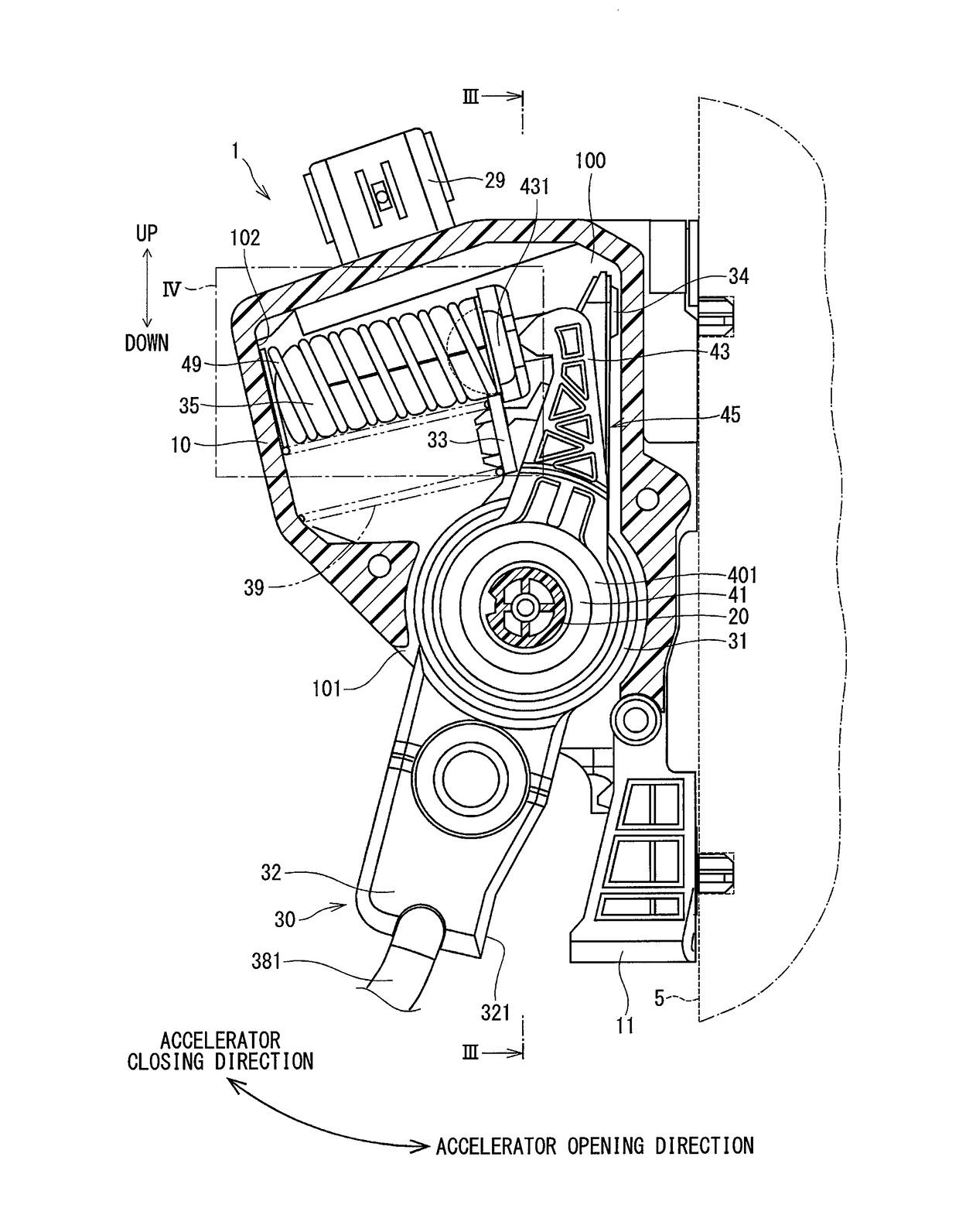
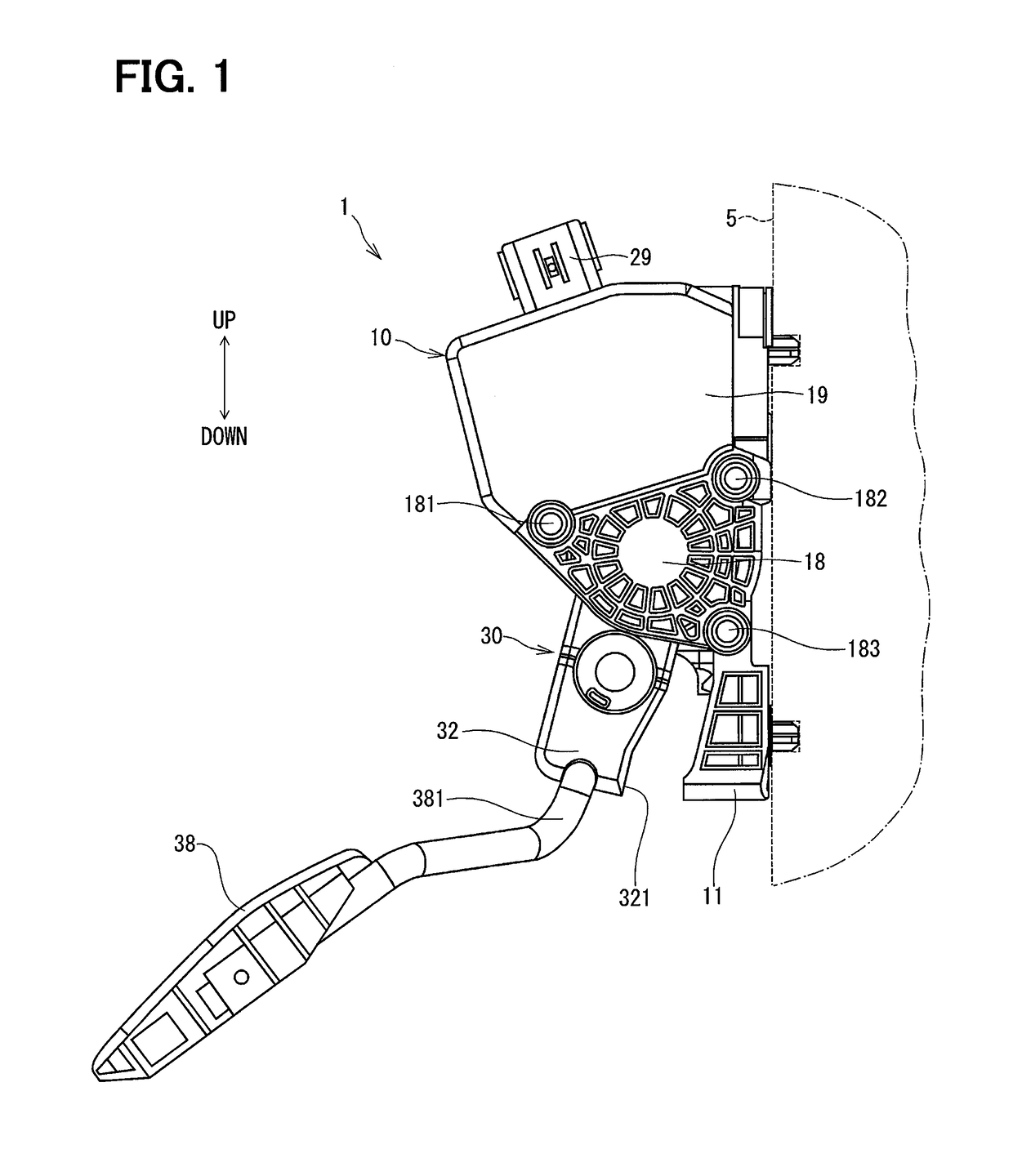
[0024]A description will be made on an accelerator device according to a first embodiment on the basis of FIGS. 1 to 6. An accelerator device 1 according to the first embodiment is an input device that is operated by a driver of a vehicle to determine a valve opening degree of a throttle valve for a vehicular engine, which is not depicted. The accelerator device 1 is of an electronic type and transmits an electric signal based on a depression amount of an accelerator pedal 38 to an electronic control device, which is not depicted. The electronic control device drives the throttle valve by using a throttle actuator, which is not depicted, on the basis of the depression amount and other information.

[0025]The accelerator device 1 includes a housing 10 corresponding to “a support portion”, a first cover 18, a second cover 19, a shaft 20, an operation member 30, the accelerator pedal 38, a pedal arm 381, a pedal spring 39, a rotation angle sensor 25 corresponding to “a rotation angle det...

second embodiment

[0070]A description will be made on an accelerator device according to a second embodiment on the basis of FIGS. 7 and 8. The second embodiment differs from the first embodiment in terms of the shape of the spring damper. Note that the substantially same portion as that in the first embodiment is denoted by the same reference sign, and the description thereon will not be made.

[0071]FIG. 7 illustrates a partial sectional view of the accelerator device of the second embodiment. The accelerator device of the second embodiment includes the spring damper 55. The spring damper 55 is arranged inside the hysteresis spring 49. The spring damper 55 is formed in an approximately pillar shape and is made of rubber. The spring damper 55 can decrease vibration of the hysteresis spring 49.

[0072]The spring damper 55 includes the main body 56 and the outward convex part 57. In FIGS. 7 and 8, an imaginary boundary between the main body 56 and the outward convex part 57 is shown in a double chain line...

third embodiment

[0078]An accelerator device according to a third embodiment is explained based on FIG. 9. The third embodiment differs in the form of a spring damper from the second embodiment. Note that the substantially same portion as that in the second embodiment is denoted by the same reference sign, and the description thereon will not be made.

[0079]FIG. 9 illustrates a sectional view of the spring damper 65 of the accelerator device of the third embodiment.

[0080]The spring damper 65 includes the main body 66 and the outward convex part 67. In FIG. 9, an imaginary boundary between the main body 66 and the outward convex part 67 is shown in a double chain line VL65 for convenience. The spring damper 65 is formed in hexagon in the cross-sectional form perpendicular to the central axis CA49 of the hysteresis spring 49.

[0081]The main body 66 is a pillar-shaped part currently formed so that the cross-section perpendicular to the central axis CA49 of the hysteresis spring 49 has a hexagon shape. Th...


PUM


Abstract

A spring damper disposed inside a coil spring includes: a main body having an outside diameter smaller than an inside diameter of a spring wire of the coil spring; and an outward convex part having a distal end located on an outer side of a cylindrical virtual plane in the radial direction, the cylindrical virtual plane passing through a center of the spring wire. When the coil spring is compressed by pressing an accelerator pedal by a driver, the outward convex part located between the adjacent spring wires prevents collision between the spring wires.

Description

CROSS REFERENCE TO RELATED APPLICATION[0001]This application is based on Japanese Patent Application No. 2015-114776 filed on Jun. 5, 2015, the disclosure of which is incorporated herein by reference.TECHNICAL FIELD[0002]The present disclosure relates to a spring damper that decreases vibration of a coil spring, and an accelerator device using the spring damper.BACKGROUND ART[0003]Conventionally, an accelerator equipment is known, which is disposed in a vehicle to control the operational status of the vehicle according to the amount of pressing an accelerator pedal by a driver. The accelerator pedal of the accelerator equipment rotates about a rotation axis of a shaft of the accelerator equipment when the driver operates. When the driver releases the accelerator pedal, the accelerator pedal rotates in the reverse direction due to a biasing force of a coil spring, and returns to the original position. For example, Patent Literature 1 describes a spring damper to decrease vibration of...

Claims


Application Information

Patent Timeline
Patent Type & Authority Applications(United States)
IPC IPC(8): F16F15/08B60K26/02F16F3/12G05G1/44G05G5/05G05G1/38
CPCF16F15/085B60K26/02F16F3/12G05G1/44G05G5/05G05G1/38G05G2505/00
Inventor KITA, TAKUTOINUZUKA, YOSHINORI
Owner DENSO CORP
Why Eureka
Try Eureka