Microdermabrasion device with skin dome measurement to adjust vacuum setting

a microdermabrasion device and vacuum setting technology, applied in the field of microdermabrasion devices, can solve the problems of non-optimal mechanical massage, higher friction, negative impact on device handling, etc., and achieve the effects of reducing lateral force, reducing lateral force, and reducing lateral for

Inactive Publication Date: 2018-05-24
KONINKLJIJKE PHILIPS NV
View PDF6 Cites 11 Cited by
  • Summary
  • Abstract
  • Description
  • Claims
  • Application Information

AI Technical Summary

Benefits of technology

[0015]With such device, the massage function (especially caused by moving the device over the skin (and in contact with the skin) in combination with the vacuum) and abrasion function (especially caused by the microdermabrasion zone, optionally in combination with moving the microdermabrasion device over the skin (and in contact with the skin)) may optimally be executed, also taking into account different types of skin, but even aspects like movement of the device or earlier treatments with the device. In this way, each type of skin and each treatment may be chosen with optimal vacuum conditions to lead to the best results, convenient to the user.
[0024]The control of the vacuum or underpressure to the inlet zone may be executed in several ways. In an embodiment, the control unit changes the vacuum provided by a pump (directly). For instance, the power supply to the pump may be controlled. Additionally or alternatively, one may keep e.g. the pump at a constant level, but control a leakage of the vacuum. A larger leakage reduces the vacuum or underpressure and a smaller leakage or no leakage increase the vacuum and (thus) reduces the pressure (larger underpressure). Hence, in an embodiment the vacuum system comprises a pump and a bypass system with a controllable vacuum leakage (from the inlet zone (to ambient)), wherein the control unit is configured to control the vacuum applied to the inlet zone by controlling the controllable vacuum leakage. Hence, the vacuum system is in fluid contact with the inlet zone, and the bypass system is also in fluid contact with the inlet zone. The bypass system may e.g. include a further channel with a controllable channel thickness (at one or more locations in the channel). For instance, the bypass system may include one or more valves for controlling the vacuum leakage. With the bypass system, it may be possible to keep the pump pumping stationary and nevertheless tuning the vacuum. For controlling the vacuum (to the inlet zone) with the vacuum system comprising the bypass system, the bypass system may include one or more of a single valve (rotating) or double valve (rotating), a non-symmetrical rotating element to control the vacuum leakage, etc. The valve may include a mechanical valve, a magnetic valve, a pressure controlled valve (pneumatically controlled), a rotating disk with holes, which hole may vary in dimensions and / or the wheel rotation speed may be varied, etc. etc. The bypass system may thus provide a controlled vacuum leakage due to a fluid contact with ambient (especially other than the inlet zone). Therefore, in embodiments the vacuum may essentially only controlled via the bypass system. This may also allow a relatively simple pump.
[0038]The gliding zone, especially the ring (especially the inner ring), may be needed for easy gliding over the skin, which will make the device easy to use. Friction can be tuned by (ring) shape, material roughness, material type, surface topography, coatings and other friction reduction methods. Lowering vacuum level also helps reducing friction, but this may be less desired because this limits the benefits (see also above). The outer zone, especially the (outer) ring, contains the abrasive texture. Abrasiveness can be tuned by texture sharpness, texture roughness, material type, ring shape, ring height, etc. The area in between the zones, especially the rings, which is further away from the skin, has an important function. It separates the gliding area from the abrasive area. It may further gives pressure to the gliding zone which may need pressure to be able to close the vacuum opening on the skin.
[0041]As indicated above, the abrasion zone has abrasive properties, such as due to microscopic structures that facilitate abrasion of the upper part of the skin. Such microscopic structures may for instance be selected from the group consisting of alumina structures, such as particles, and diamond structures, such as diamond particles. These structures are comprised by the abrasion rim, i.e. are attached or part of the rim. Especially, the microdermabrasion area comprises abrasive structures, such as particulate material, attached to the microdermabrasion area having mean dimensions in the range of 1-1000 μm, such as 2-300 μm, like 5-80 μm or 120-200 μm. These dimensions may also apply when a gas flow with abrading particles is applied. Alternatively or additionally, the microscopic structures may for instance be selected from the group consisting of silicon carbide structures, such as silicon carbide particles, and metal nitride structures, such as metal nitride particles. Alternatively or additionally, the microscopic structures may for instance be selected from the group consisting of metal oxide structures, such as aluminum oxide particles and aluminum oxide structures. Further options of microscopic structures may for instance be selected from the group consisting of diamond structures, boron nitride structures, silicon carbide structures (see also above), glass beads, steel grit structures, other metal grit structures, zirconium oxide structures, and quartz structures. Combinations of different kind of structures, both in chemical composition and / or dimensions, may also be applied. In an embodiment, the quotient of the number of abrasive particles at the channel rim is especially 10% or less, more especially 5% or less, even more especially 1% or less of the number of abrasive particles comprised by the microdermabrasion area, especially 0.1% or less. In an embodiment, such abrasive particles are not comprised at all by the channel rim. The lower content or absence of such particles by the channel rim may facilitate gliding. The numbers given here as especially provided as an indication for certain embodiments to indicate the difference between the functionality of the channel rim and the microdermabrasion area.

Problems solved by technology

For instance, a too high underpressure can cause the skin to be extended too much resulting in side effects like bruising or blisters whereas a too low underpressure leads to a non-optimal mechanical massage.
Furthermore, a too high underpressure may create a higher friction during movement which can negatively impact the device handling.
Further, the underpressure or vacuum may affect the abrading effect and / or the massage effect.
Using the same underpressure settings at all treatment locations may result in unpleasant and more severe treatments on those delicate areas.
Current available microdermabrasion devices do not offer a large variety in underpressure settings and determining the optimal setting is very difficult for a consumer.

Method used


Image

  • Microdermabrasion device with skin dome measurement to adjust vacuum setting
  • Microdermabrasion device with skin dome measurement to adjust vacuum setting
  • Microdermabrasion device with skin dome measurement to adjust vacuum setting

Examples


Embodiment Construction

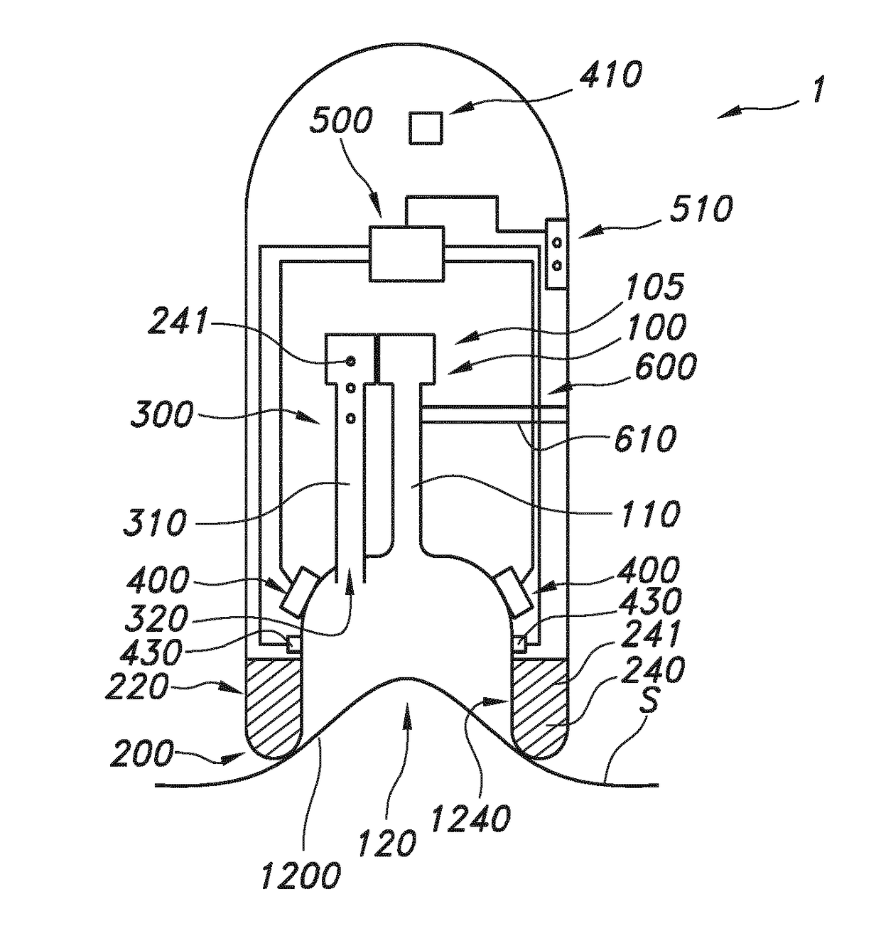
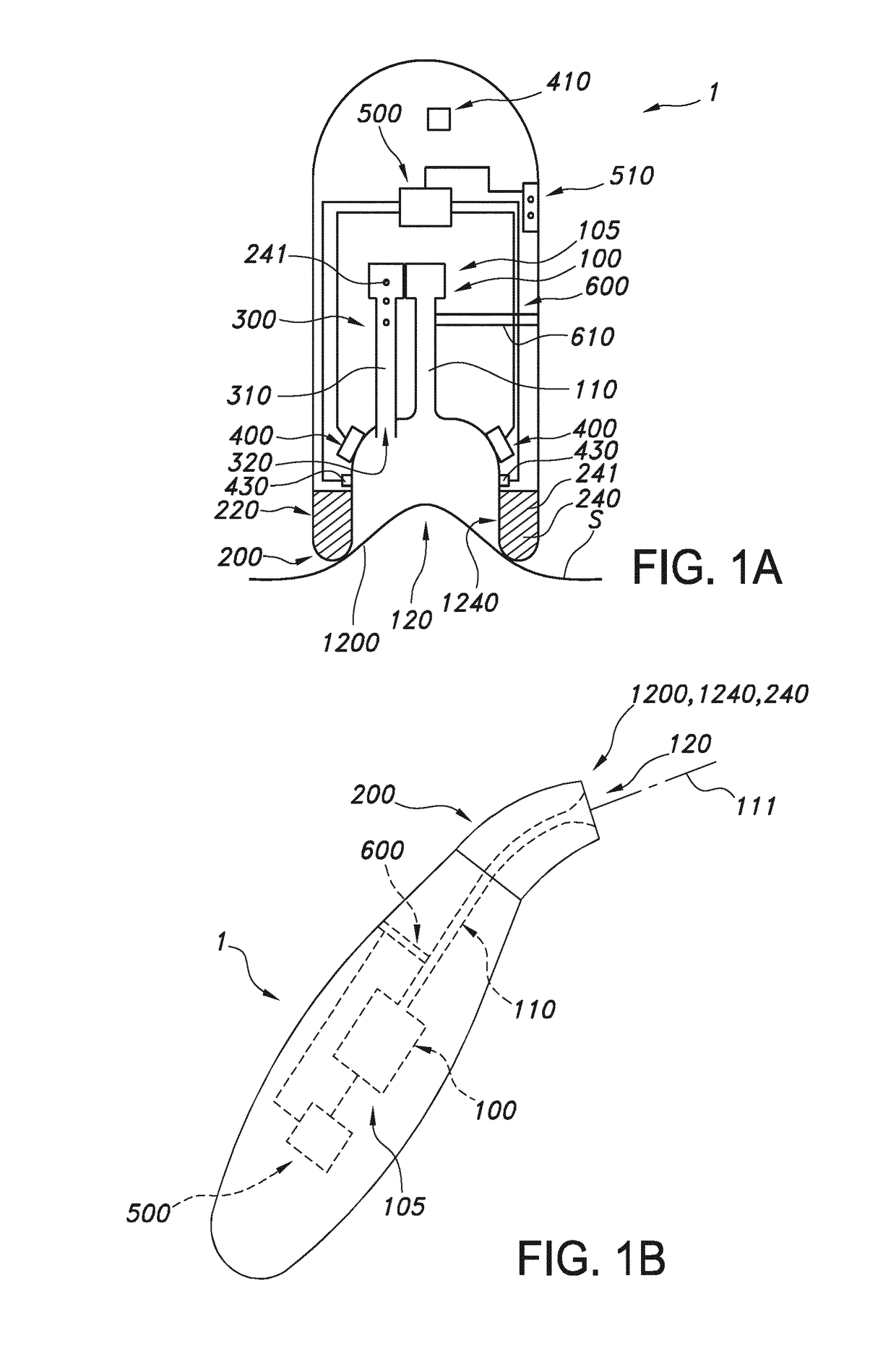
[0052]FIG. 1a schematically depicts an embodiment of the microdermabrasion device 1 including optional variants that may be included or of which some may and others may not be included dependent upon the specific embodiment desired. FIG. 1a shows microdermabrasion device 1 comprising a vacuum system 100 and a device tip 200. Here, the vacuum system 100 comprises a channel 110 with a channel inlet 120 at an inlet zone 1200 of the device tip 200. The vacuum system 100 is configured to apply a vacuum to the inlet zone 1200. To this end, the vacuum system 100 also comprises a pump 105. The channel opening, may provide a vacuum area in the range of 10-400 mm2, such as at least 45 mm2, especially in the range of 45-400 mm2. Further, the inlet zone 1200 comprises a sensor 400 configured to measure a skin parameter of a part of a skin in the inlet zone 1200 and to provide a corresponding sensor signal. The skin is indicated as line with reference S, and is of course not a part of the microd...


PUM


Abstract

The invention provides a microdermabrasion device (1) comprising a vacuum system (100) and a device tip (200), wherein the vacuum system (100) is in fluid communication with a channel inlet (120) at an inlet zone (1200) of the device tip (200), wherein the vacuum system (100) is configured to apply a vacuum to the inlet zone (1200), wherein the inlet zone (1200) further comprises an sensor (400) configured to measure a skin parameter of a part of a skin in the inlet zone (1200) and to provide a corresponding sensor signal, wherein the device tip (200) further comprises a microdermabrasion zone (1240) configured to abrade a part of said skin, and wherein the microdermabrasion device (1) further comprises a control unit (500) configured to control the vacuum as function of sensor signal information derived from the sensor signal and a predetermined relation between the sensor signal information and a vacuum setting.

Description

FIELD OF THE INVENTION[0001]The invention relates to a microdermabrasion device and to a method for the controlled removal of at least part of the stratum corneum with such device.BACKGROUND OF THE INVENTION[0002]Microdermabrasion devices are known in the art. U.S. Pat. No. 6,241,739 describes for instance a treatment tool and tissue collection system, for removal of outer layers of skin to provide a revitalized, fresh skin surface, and a method of using same, comprising an abrasive tipped tool mounted on the end of a tube, said tube being connected to a source of vacuum. The vacuum aids in maintaining intimate contact between the abrasive tip and the skin during the treatment process and transports the removed tissue to a collection container.[0003]Especially, this document describes a device for removing portions of the outer layers of skin comprising a source of a vacuum, and a tube with an abrasive treatment tip thereon for dislodging cells from a surface being treated, the tube...

Claims


Application Information

Patent Timeline
Patent Type & Authority Applications(United States)
IPC IPC(8): A61B17/54
CPCA61B17/545A61B2017/00561A61B2217/005A61B17/54
Inventor BEIJENS, LINDA GOVERDINA MARIAJURNA, MARTINJANSEN, MARJOLEIN YVONNEPEETERS, FELIX GODFRIED PETER
Owner KONINKLJIJKE PHILIPS NV
Why Eureka
Try Eureka