Magnetic coupling assembly for coupling stir bar in magnetic stirrer mixer and magnetic stirrer mixer using the same
a technology magnetic coupling assembly, which is applied in the field of magnetic stirrer mixers using the same magnetic coupling assembly and the magnetic coupling assembly for coupling stir bar, can solve the problems of limiting the mixing performance of high speed, the uncoupling the spin-out of the stir bar, and the magnet speed that is too fast, etc., to achieve stable running of the magnetic stirrer, expand the effective radius of mixing, and high rotation speed
- Summary
- Abstract
- Description
- Claims
- Application Information
AI Technical Summary
Benefits of technology
Problems solved by technology
Method used
Image
Examples
example 1
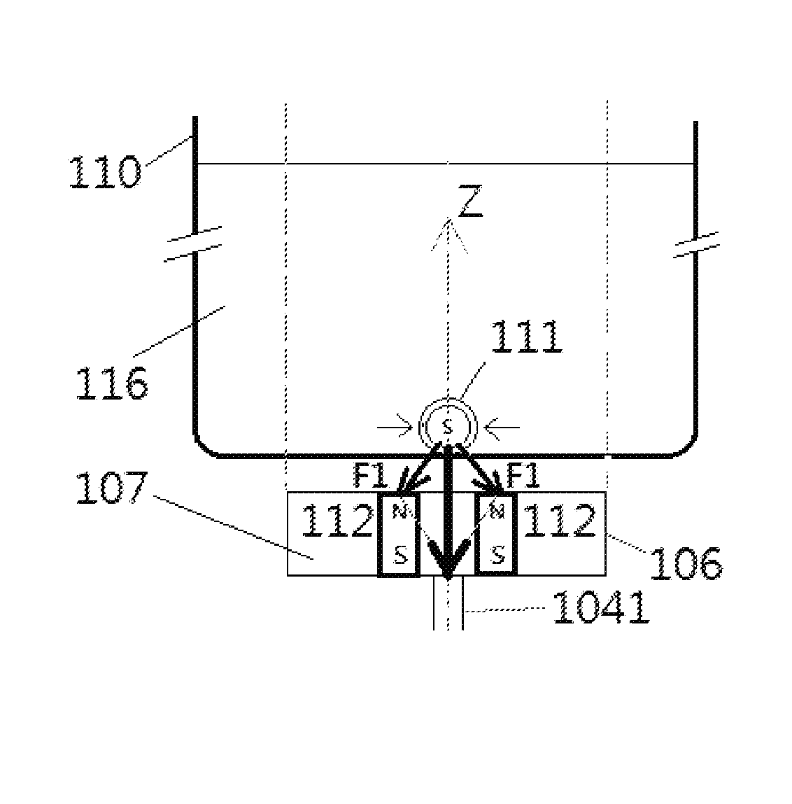
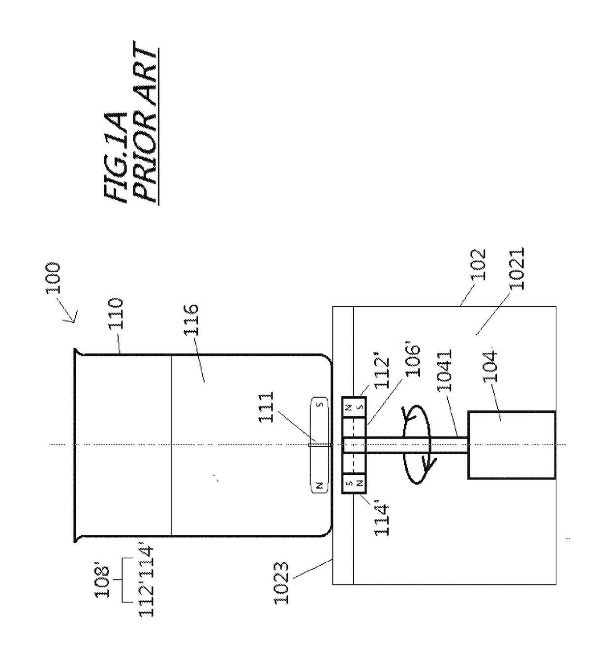
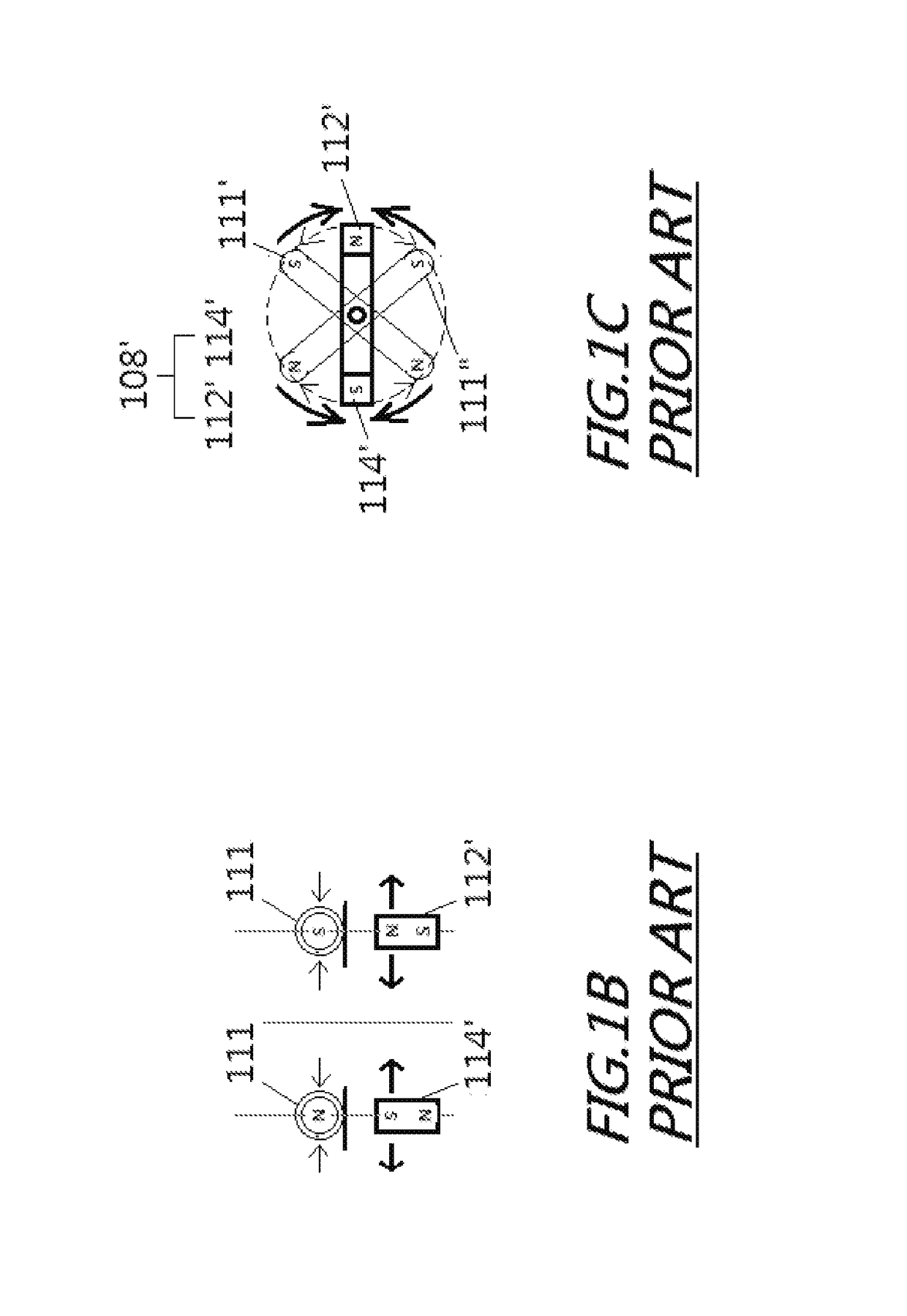
[0047]By referring to FIG. 3D, a rectangular plastic block 25 by 48 mm is used to embed four small neodymium-iron-boron disc type drive magnets of 5 mm diameter and 5 mm thickness with a relatively small size of 14 mm by 25 mm for the four-corner cage. If only a diagonal pair of drive magnets is embedded, the conventional coupling shown in FIGS. 1A-1C is obtained. Three kinds of Teflon-coated stir bars of 8 mm diameter and of various lengths L and shapes: (A) L=38 mm, octagonal cross section with a central integrated pivot ring (like the stir bar 111 shown in FIG. 1A); (B) L=27 mm, smooth cylindrical shape; and (C) L=44 mm; smooth elliptical shape were tested for effectiveness of magnetic coupling by this invention versus the conventional magnetic coupling. The effectiveness of magnetic coupling is expressed as maximum stirrer speed attainable and minimum spin-out speed upon instant step-up from standstill. The coupling space between the two was about 5-6 mm, which includes the comb...
example 2
[0048]In reference to FIG. 3D, the same rectangular plastic block as in Example 1 is used in this Example whereas embedded therein are four medium size neodymium-iron-boron disc type drive magnets 108 of 8 mm diameter and 5 mm thickness with a relatively larger cage size of 20 mm by 43 mm. The rest of the MCA design and tests are the same as Example 1. The test results are listed below:
TABLE 2Magnetic coupling assembliesSingle coupling pairDual coupling pairs of this29-45 mm reach*invention, 27-43 mm reach*Max. stirrerMin. spin-Max. stirrerMin. spin-Measure-speedout speedspeedout speedment(rpm)(rpm)(rpm)(rpm)Stir bar A,400Too low to2,9001,40038 mm longmeasurereliablyStir bar B,Too low to1,2001,10027 mm longmeasurereliablyStir bar C,1,9009002,0001,00044 mm long*See note under Table 1.
example 3
[0049]In reference to FIG. 4A, a drive magnet disc 106 of 48 mm diameter and embedded with four neodymium-iron-boron type disc magnets of 10 mm diameter and 12 mm thickness with a cage size of 25 mm by 36 mm. If only the diagonal pair of magnets, e.g., P1 and P4, is embedded as in Example 1, the conventional coupling of FIG. 1 is obtained. Due to the design differences, the coupling space between the magnets and the stir bar in this example is about 7-8 mm, which includes the combined thickness of the glass beaker bottom plus the platform 1023 and the air space in between. A 3100 rpm brushless DC motor with digital tachometer rpm readout to ±1 rpm, a 10-turn precision rheostat and an on-off instant motor-breaking toggle switch was used. The rest of the MCA design and tests are the same as in Example 1. The test results are listed below:
TABLE 3Magnetic coupling assembliesSingle coupling pairDual coupling pairs of this20-40 mm reach*invention, 16-36 mm reach*Max. stirrerMin. spin-Max....
PUM
 Abstract
Description
Claims
Application Information
 - R&D
- Intellectual Property
- Life Sciences
- Materials
- Tech Scout
- Unparalleled Data Quality
- Higher Quality Content
- 60% Fewer Hallucinations
Browse by: Latest US Patents, China's latest patents, Technical Efficacy Thesaurus, Application Domain, Technology Topic, Popular Technical Reports.
© 2025 PatSnap. All rights reserved.Legal|Privacy policy|Modern Slavery Act Transparency Statement|Sitemap|About US| Contact US: help@patsnap.com


