Automated equipment system, emergency stop terminal, and operation terminal control method

a technology of automatic equipment and emergency stop terminal, which is applied in the direction of vehicle position/course/altitude control, process and machine control, instruments, etc., can solve the problems of difficulty or substantially impossible to provide the operation terminal with a function, automatic equipment to make an emergency stop, and not desirable from the point of view of maintenance work efficiency, etc., to achieve excellent workability

Active Publication Date: 2018-05-24
MURATA MASCH LTD
View PDF18 Cites 20 Cited by
  • Summary
  • Abstract
  • Description
  • Claims
  • Application Information

AI Technical Summary

Benefits of technology

[0039]According to preferred embodiments of the present invention, it is possible t...

Problems solved by technology

Furthermore, when a general purpose portable terminal device that is available on the market, for example, is used as the operation terminal that operates the automated equipment via wireless communication, it is difficult or substan...

Method used


Image

  • Automated equipment system, emergency stop terminal, and operation terminal control method
  • Automated equipment system, emergency stop terminal, and operation terminal control method
  • Automated equipment system, emergency stop terminal, and operation terminal control method

Examples


Embodiment Construction

[0051]Hereinafter, automated equipment systems according to preferred embodiments of the present invention will be described with reference to the drawings. It should be noted that the respective figures are schematic diagrams and are not necessarily precise illustrations.

[0052]Furthermore, the preferred embodiments described below are generic or specific examples. The numerical values, shapes, materials, structural components, the arrangement and connection of the structural components, etc., shown in the following preferred embodiments are mere examples, and are not intended to limit the present invention. Furthermore, among the structural components in the following preferred embodiments, structural components not recited in any one of the independent claims defining the most generic concepts are described as arbitrary structural components.

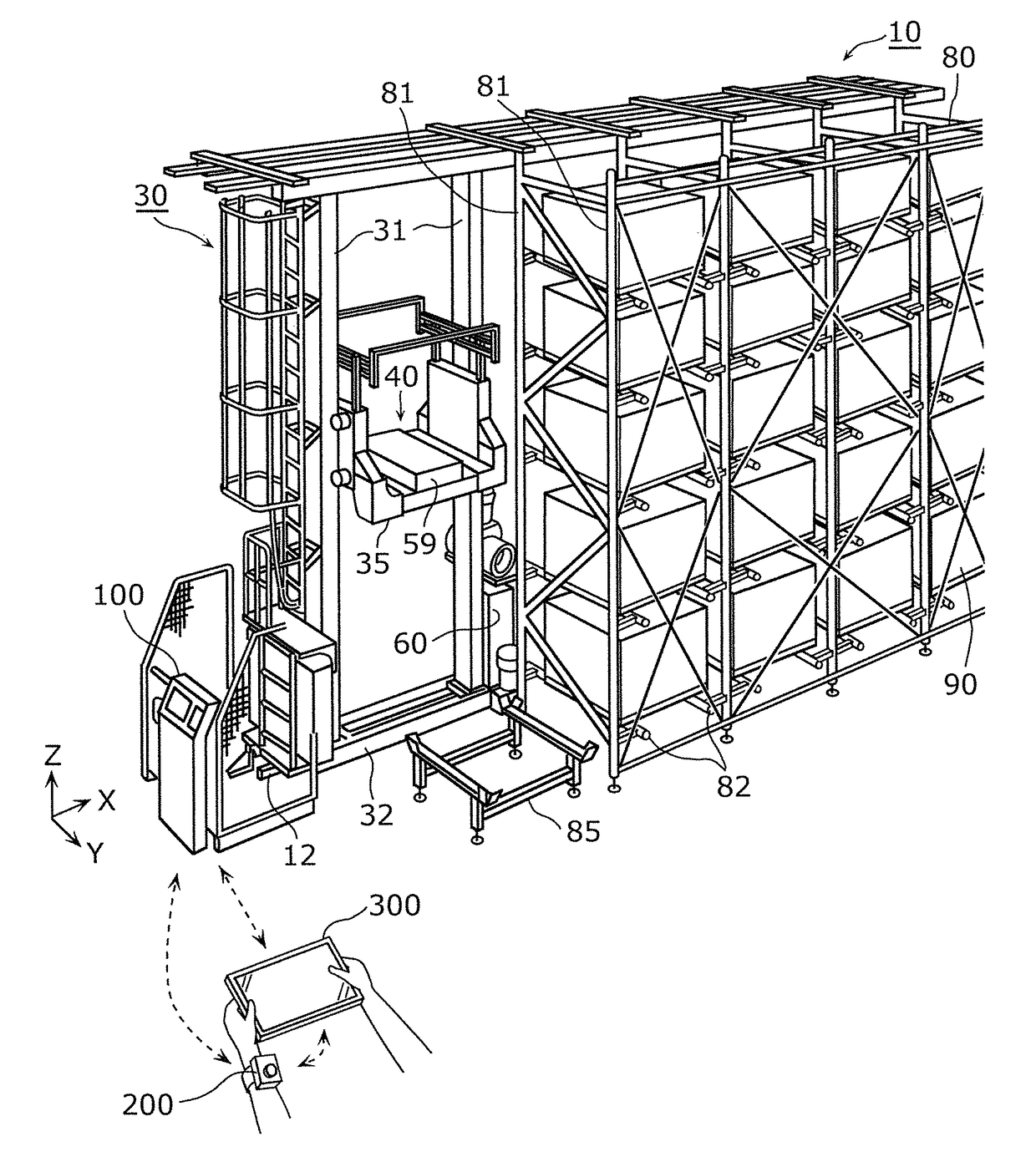
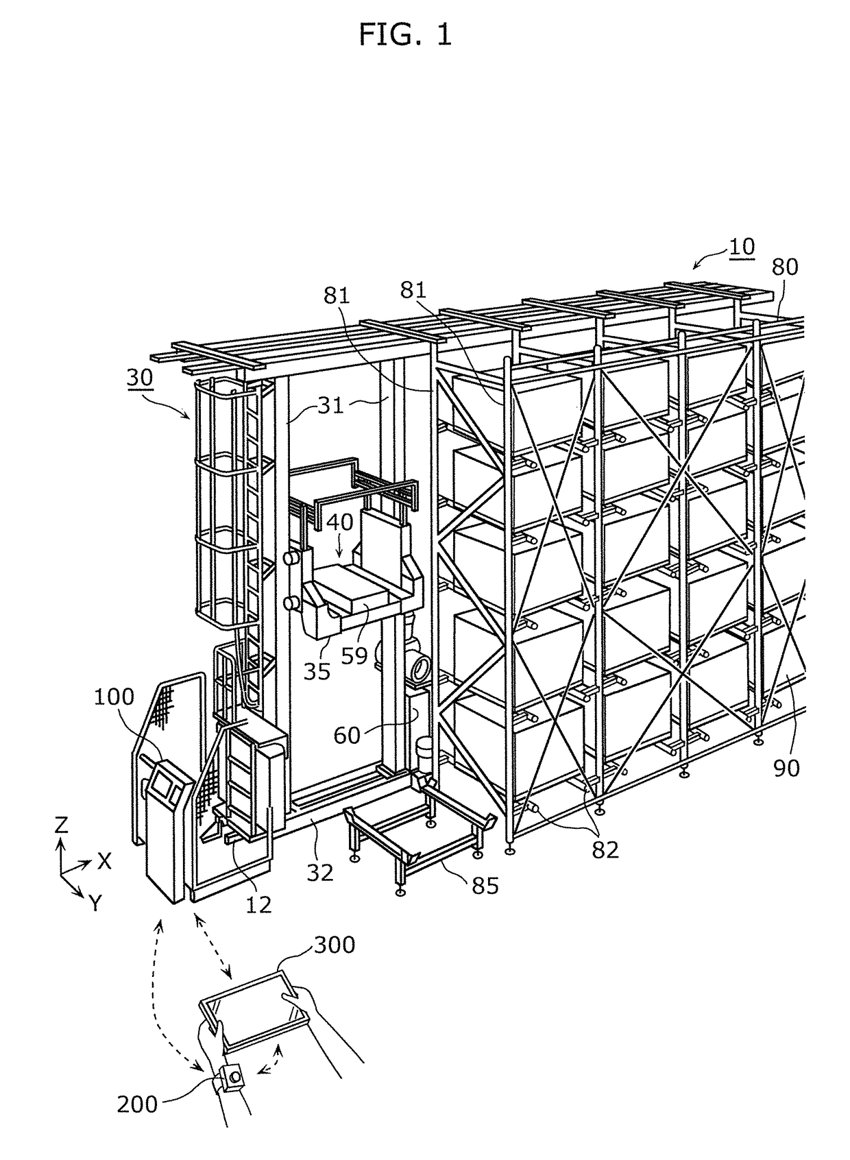
[0053]First, the outline configuration of an automated equipment system 10 according to a preferred embodiment of the present invention will ...


PUM


Abstract

An automated equipment system including a stacker crane includes an emergency stop terminal and a controller that executes operational control of the stacker crane. The emergency stop terminal includes an emergency stop button; and a first communicator that performs wireless communication with the controller, and changes a state of the wireless communication with the controller when the emergency stop button is operated. The controller: executes the operational control of the stacker crane according to a command from an operation terminal, when wireless communication with both the emergency stop terminal and the operation terminal, which transmits a command for the operational control of the stacker crane is possible; and stops operation of the stacker crane when the state of the wireless communication with the first communicator is changed.

Description

BACKGROUND OF THE INVENTION1. Field of the Invention[0001]The present invention relates to an automated equipment system including automated equipment, a controller that executes operational control of the automated equipment, and an emergency stop terminal that causes the automated equipment to make an emergency stop.2. Description of the Related Art[0002]Conventionally, there are automated equipment systems that include automated equipment such as a transport carriage for unmanned transportation of cargo. In such an automated equipment system, an operator can execute remote control of the automated equipment via wireless communication by performing input operations on a portable operation terminal, for example.[0003]For example, Japanese Unexamined Patent Application Publication No. 2009-260773 discloses a communication system that controls equipment such as a transport carriage, using a remote control. In this communication system, communication is carried out between the remote ...

Claims


Application Information

Patent Timeline
IPC IPC(8): B65G1/04G05D1/00G05D1/02
CPCB65G1/0421G05D1/0066G05D1/0016G05D1/0223G05D2201/0216G05D1/0276B25J13/06G05D1/0033B65G2207/40B25J19/06
Inventor MURANAKA, TAKESHI
Owner MURATA MASCH LTD
Why Eureka
Try Eureka