Method of Correcting Rotor Imbalance and Wind Turbine Thereof

a technology of rotor imbalance and wind turbine, which is applied in the direction of wind motor control, wind power generation, wind power generation, etc., can solve the problems of rotor imbalance, rotor imbalance, deformation of wind turbine blade aerodynamics, etc., and achieve the effect of reducing mass imbalance and saving time and cost of the correction process

Active Publication Date: 2018-05-24
ENVISION ENERGY DENMARK
View PDF6 Cites 24 Cited by
  • Summary
  • Abstract
  • Description
  • Claims
  • Application Information

AI Technical Summary

Benefits of technology

[0096]The control system is further configured to use the imbalance factor and imbalance phase to calculate a mass correction as described above, once the rotor is aerodynamically balanced. A mathematical or aeroelastic model may be used to determine an initial value of the parameters used to calculate the mass moment required to correct the mass imbalance. Unlike the embodiment of U.S. Pat. No. 8,261,599 B2, the control system is able to calculate this mass moment using the same equation (1), (3) as used to calculate the correction angle by simply changing the set of parameters in the equation as described above. Alternatively, the control system is configured to receive one of more of these parameters from another wind turbine control system and then calculate the mass moment correction using these parameters. This allows the required balancing mass to be determined without having to place test weights on the outside of the wind turbine blade, thus saving time and costs of the correction process. Furthermore, this provides a simplified correction process as the par

Problems solved by technology

Rotor imbalances may be caused by uneven weight distribution in the wind turbine blade (mass imbalance) or deviations from the normal or ideal aerodynamic properties (aerodynamic imbalance).
Mounting and manufacturing tolerances may also produce rotor imbalance if the wind turbine blade is mounted with a tolerance in the mounting angle or if the mounting interface of the hub or the blade root is not planar.
It is known that erosions on the leading edge profile due to wear, cracks in the outer surface due to lighting strikes, built-up of ice or other particles on the outer surface, or other conditions may degrade the aerodynamics of the wind turbine blades.
Any rotor imbalance will lead to vibrations and dynamic loads in the rotor and in the rest of the wind turbine, thereby reducing the lifetime of

Method used


Image

  • Method of Correcting Rotor Imbalance and Wind Turbine Thereof
  • Method of Correcting Rotor Imbalance and Wind Turbine Thereof
  • Method of Correcting Rotor Imbalance and Wind Turbine Thereof

Examples


first embodiment

[0036]In a first embodiment, the control parameters mentioned above are measured within at least two time windows, e.g. the first and second time windows, in an initial or first run of the correction process. The control system then determines an imbalance factor and an imbalance phase for each of the first and second time windows. A first correction action is calculated and applied after the first measurement. A second control action is afterwards calculated and applied after the second measurement. This also enables the parameters used to calculate this correction action to be adjusted to the changing rotor imbalance as described later. In any subsequent (second, third, fourth, etc.) runs of the correction process, the control parameters are measured within a least one time window, e.g. a third time window, and thus the control system determines at least one (third) imbalance factor and / or imbalance phase based on this third measurement optionally using these adjusted parameters.

[...

second embodiment

[0045]In a second embodiment, the control parameters mentioned above are measured within at least three time windows, e.g. the first, second and third time windows, in an initial or first run of the correction process. The control system then determines an imbalance factor and an imbalance phase for each of the first, second and third time windows. A first deterministic imbalance or correction action, e.g. the first rotor imbalance, is applied to the rotor after the first measurement. A second deterministic imbalance or correction, e.g. the second rotor imbalance, is applied to the rotor after the second measurement. The deterministic imbalances may be any aerodynamic and / or mass imbalance. The control system then calculates a required correction action based on these first, second and third imbalance factors and imbalance phases. This also enables these parameters used to calculate the correction action to be adjusted to the changing rotor imbalance as described later. In any subse...

third embodiment

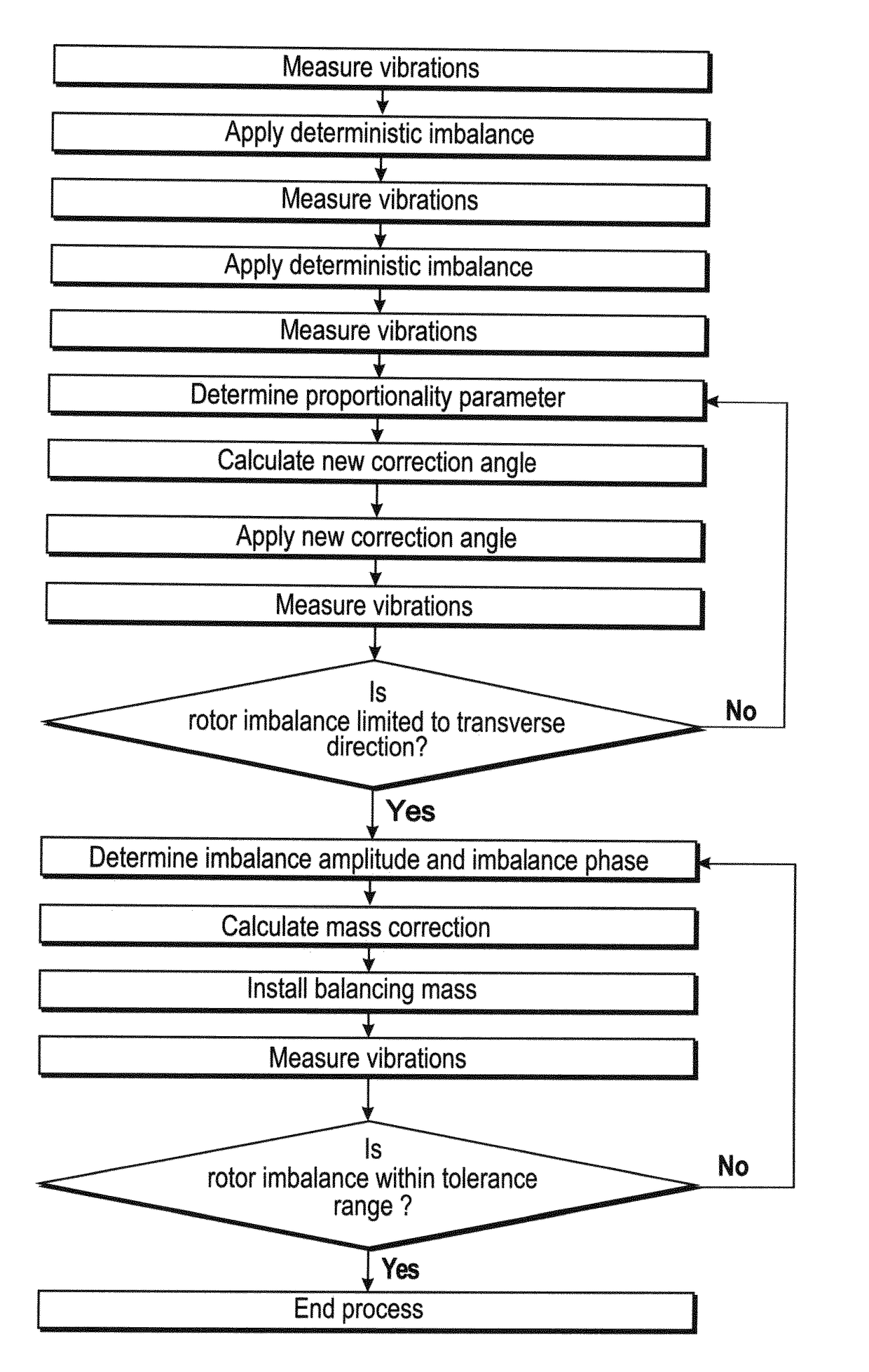
[0108]FIG. 7 shows the correction method according to the invention,

[0109]FIG. 8 shows three graphs of the amplitude of an exemplary measured rotor imbalance before and after a first and second run of the correction process,

[0110]FIG. 9 shows three graphs of the imbalance factor of the rotor imbalance of FIG. 8 before and after the first and second run of the correction process, and

[0111]FIG. 10 shows three graphs of the imbalance phase of the rotor imbalance of FIG. 8 before and after the first and second run of the correction process.

[0112]In the following text, the figures will be described one by one and the different parts and positions seen in the figures will be numbered with the same numbers in the different figures. Not all parts and positions indicated in a specific figure will necessarily be discussed together with that figure.


PUM


Abstract

The present invention relates to a method of correcting rotor imbalance and a wind turbine thereof. The correction method comprises measuring the vibrations within at least one time window and determining an imbalance factor and an imbalance phase. The values of the parameters in the equation for calculating the correction action are then updated based on the imbalance factor and an imbalance phase. A correction angle for each of the wind turbine blades is calculated using these adjusted parameters. The correction angle is used to aerodynamically balance the rotor, and a model may be used to determine the initial values of the parameters. Another imbalance factor and imbalance phase is determined based on another set of measurements. This imbalance factor is then used to calculate a mass moment for correcting the mass imbalance in the wind turbine blades. The weight and location of a balancing mass is finally calculated based on this mass moment and installed in the respective wind turbine blades.

Description

FIELD OF THE INVENTION[0001]The present invention relates to a method for correcting a rotor imbalance in a wind turbine comprising a wind turbine tower, a nacelle, and a generator connected to a rotatable rotor with at least two wind turbine blades.[0002]The present invention also relates to a wind turbine comprising a wind turbine tower, a nacelle, a generator connected to a rotatable rotor with at least two wind turbine blades, and a control system configured to execute the control method mentioned above.BACKGROUND OF THE INVENTION[0003]It is well-known that a wind turbine rotor needs to be balanced during rotation to achieve a high energy yield and to reduce vibrations in the wind turbine, including the rotor, to a minimum. Rotor imbalances may be caused by uneven weight distribution in the wind turbine blade (mass imbalance) or deviations from the normal or ideal aerodynamic properties (aerodynamic imbalance). Mounting and manufacturing tolerances may also produce rotor imbalan...

Claims


Application Information

Patent Timeline
IPC IPC(8): F03D13/35F03D7/02
CPCF03D13/35F03D7/0224F03D7/024F03D7/0296Y02E10/72
Inventor PEDERSEN, KELD STEFAN
Owner ENVISION ENERGY DENMARK
Why Eureka
Try Eureka