X-ray illumination system with multiple target microstructures

a microstructure, x-ray technology, applied in x-ray tubes, x-ray tube targets and convertors, nuclear engineering, etc., can solve the problem of still limits on the ultimate x-ray brightness that may be achieved with micro-focus x-ray sources

Active Publication Date: 2018-05-24
SIGRAY INC
View PDF0 Cites 25 Cited by
  • Summary
  • Abstract
  • Description
  • Claims
  • Application Information

AI Technical Summary

Benefits of technology

[0008]The present technology, roughly described, includes an x-ray illumination beam system that includes an electron emitter and a target having one or more target microstructures, collectively referred to as an x-ray s

Problems solved by technology

Despite these developments, there are still limits on the ultimate x

Method used


Image

  • X-ray illumination system with multiple target microstructures
  • X-ray illumination system with multiple target microstructures
  • X-ray illumination system with multiple target microstructures

Examples


Embodiment Construction

1. Exemplary Embodiment

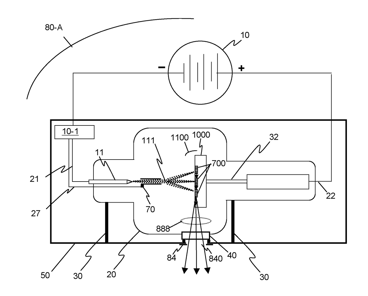
[0071]FIG. 6 illustrates an embodiment of a reflective x-ray system 80-A according to the invention. As in the prior art reflective x-ray system 80 described above, the source comprises a vacuum environment (typically 10−6 torr or better) commonly maintained by a sealed vacuum chamber 20 or active pumping, and manufactured with sealed electrical leads 21 and 22. The source 80-A will typically comprise mounts 30, and the housing 50 may additionally comprise shielding material, such as lead, to prevent x-rays from being radiated by the source 80-A in unwanted directions.

[0072]Inside the chamber 20, an emitter 11 connected through the lead 21 to the negative terminal of a high voltage source 10 serves as a cathode and generates a beam of electrons 111. Any number of prior art techniques for electron beam generation may be used for the embodiments of the invention disclosed herein. Additional known techniques used for electron beam generation include heating for t...


PUM


Abstract

An x-ray illumination beam system includes an electron emitter and a target having one or more target microstructures. The one or more microstructures may be the same or different material, and may be embedded or placed atop a substrate formed of a heat-conducting material. The x-ray source may emit x-rays towards an optic system, which can include one or more optics that are matched to one or more target microstructures. The matching can be achieved by selecting optics with the geometric shape, size, and surface coating that collects as many x-rays as possible from the source and at an angle that satisfies the critical reflection angle of the x-ray energies of interest from the target. The x-ray illumination beam system allows for an x-ray source that generates x-rays having different spectra and can be used in a variety of applications.

Description

CROSS-REFERENCE TO RELATED APPLICATIONS[0001]The Present patent application is a continuation-in-part of U.S. patent application Ser. No. 15 / 166,274, filed May 27, 2016 and entitled DIVERGING X-RAY SOURCES USING LINEAR ACCUMULATION, which is a continuation-in-part of U.S. patent application Ser. No. 14 / 999,147, filed Apr. 1, 2016 and entitled X-RAY SOURCES USING LINEAR ACCUMULATION, which claims the benefit of U.S. Provisional Patent Application No. 62 / 141,847, filed Apr. 1, 2015 and entitled ADDITIONAL X-RAY SOURCE DESIGNS USING MICROSTRUCTURED TARGETS, and U.S. Provisional Patent Application No. 62 / 155,449, filed Apr. 30, 2015, and entitled X-RAY TARGET FABRICATION, both of which are incorporated herein by reference in their entirety; and which in turn is also a continuation-in-part of U.S. patent application Ser. No. 14 / 490,672, filed Sep. 19, 2014 and entitled X-RAY SOURCES USING LINEAR ACCUMULATION, which claims the benefit of U.S. Provisional Patent Application Nos. 61 / 880,151...

Claims


Application Information

Patent Timeline
IPC IPC(8): H01J35/10H01J35/14H01J35/26H01J35/30G21K1/06
CPCH01J35/105H01J35/14H01J35/26H01J35/30G21K1/067H01J35/108H01J2235/086G21K2201/064H01J2235/1204H01J35/10H01J35/101H01J35/305H01J35/147H01J2235/088
Inventor YUN, WENBINGLEWIS, SYLVIA JIA YUNKIRZ, JANOSREYNOLDS, DAVID CHARLESLYON, ALAN FRANCIS
Owner SIGRAY INC
Why Eureka
Try Eureka