Capacitive switch device
- Summary
- Abstract
- Description
- Claims
- Application Information
AI Technical Summary
Benefits of technology
Problems solved by technology
Method used
Image
Examples
first embodiment
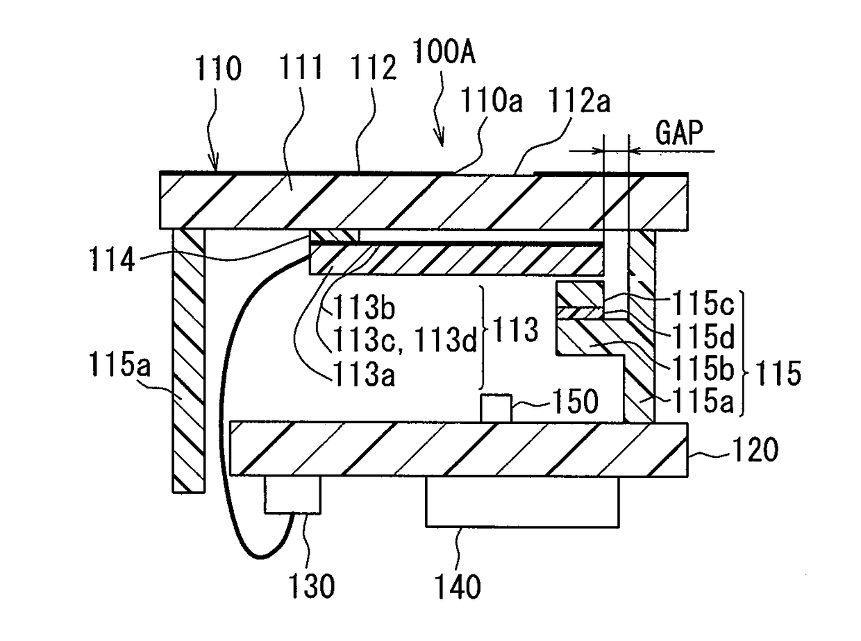
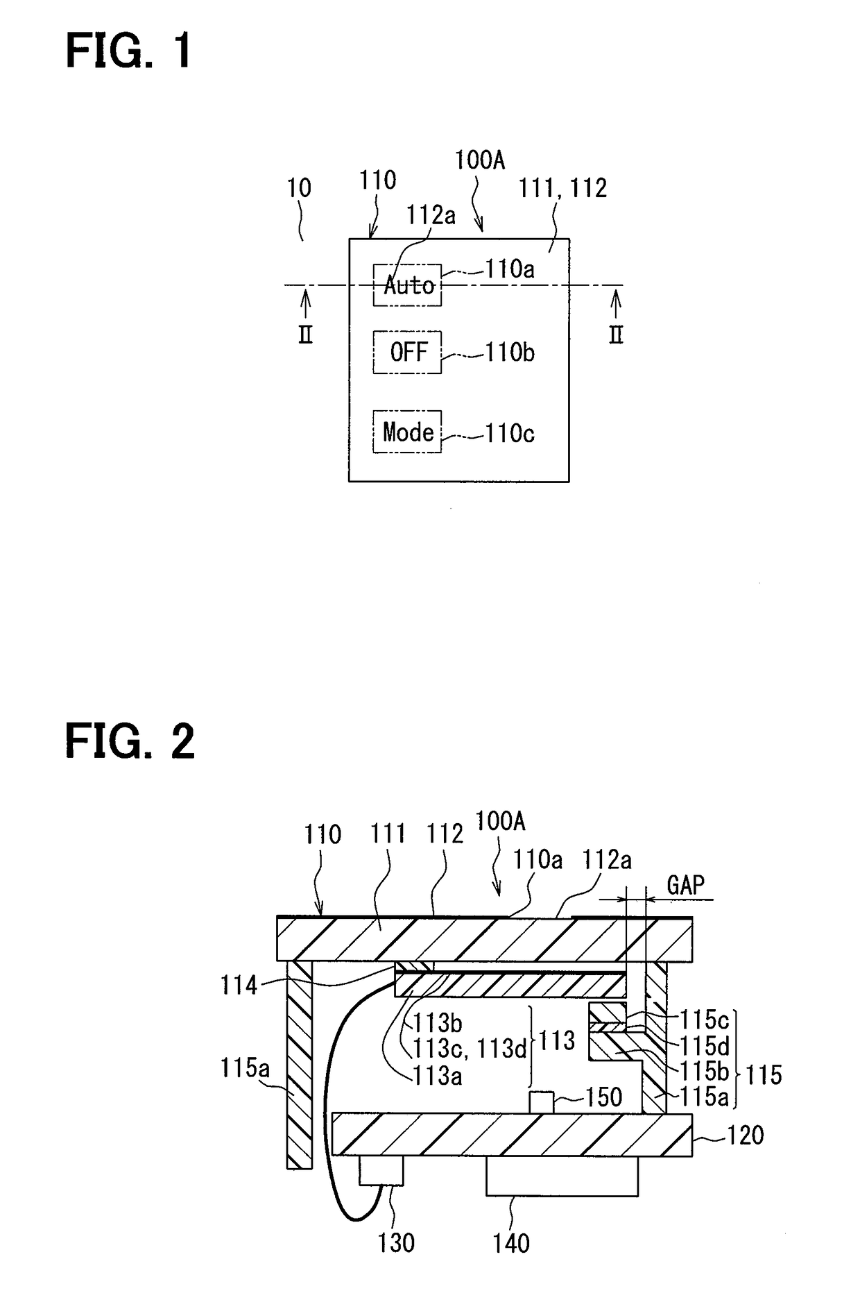
[0024]A first embodiment of the present disclosure will be described using FIG. 1 through FIG. 3. A capacitive switch device (hereinafter, referred to simply as the switch device) 100A of the present embodiment is used to input an operating condition into an air-conditioning device as an example of a predetermined device equipped to a vehicle. The switch device 100A includes an input portion 110, a substrate 120, a connector 130, a detection IC 140, an illumination LED 150, and so on.
[0025]The input portion 110 is a portion through which a driver (user) inputs an operating condition into the air-conditioning device by an operation with a finger. The input portion 110 is located at an easy-to-operate position for the driver in an instrument panel 10 of the vehicle. Phrases, “a finger operation” and “operation or operated with a finger”, referred to herein mean an operation to touch any one of switches 110a through 110c described below with a finger, which corresponds to a touch opera...
second embodiment
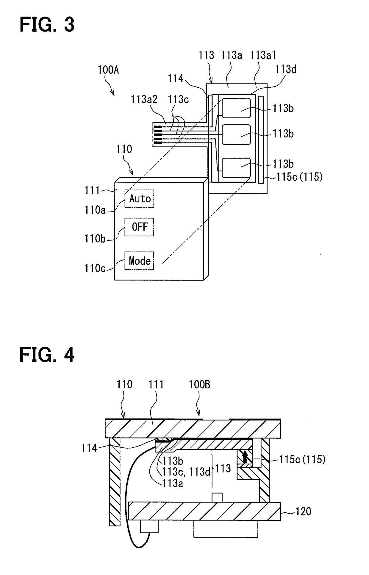
[0051]A switch device 100B of a second embodiment is shown in FIG. 4. The switch device 100B of the second embodiment is different from the switch device 100A of the first embodiment above in that a soft member 115c pushes an other-end portion of a base film 113a toward an operation panel 111. An arrow of FIG. 4 indicates a pushing direction.
[0052]A tip-end surface of the soft member 115c is in contact with a surface of the base film 113a on a side of a substrate 120 and applies a predetermined pushing force to the base film 113a toward the operation panel 111. No gap or a fine gap is provided between the operation panel 111 and an electrode portion 113b and the base film 113a is maintained in a posture along surfaces of the operation panel 111. Even under a pushing force applied by the soft member 115c, the base film 113a is allowed to move due to thermal expansion and thermal contraction in an in-plane direction of the base film 113a in a same manner as in the first embodiment abo...
third embodiment
[0055]A switch device 100C of a third embodiment is shown in FIG. 5. The switch device 100C of the third embodiment is different from the switch devices 100A and 100B of the first and second embodiments above in that a positioning portion which fixes a position of a base film 113a with respect to an operation panel 111 is additionally provided.
[0056]The positioning portion is provided to the operation panel 111 and has a rod-shaped positioning pin 111a extending toward the base film 113a and a positioning hole 113e provided to the base film 113a to let the positioning pin 111a pass through.
[0057]The positioning pin 111a and the positioning hole 113e are provided to correspond to a region where a double-faced adhesive tape 114 is provided. More specifically, the positioning pin 111a and the positioning hole 113e are provided in portions (two portions) located at both ends of the double-faced adhesive tape 114 in a longitudinal direction.
[0058]Owing to the configuration as above, the ...
PUM
 Abstract
Description
Claims
Application Information
 - R&D
- Intellectual Property
- Life Sciences
- Materials
- Tech Scout
- Unparalleled Data Quality
- Higher Quality Content
- 60% Fewer Hallucinations
Browse by: Latest US Patents, China's latest patents, Technical Efficacy Thesaurus, Application Domain, Technology Topic, Popular Technical Reports.
© 2025 PatSnap. All rights reserved.Legal|Privacy policy|Modern Slavery Act Transparency Statement|Sitemap|About US| Contact US: help@patsnap.com


