Zero-quiescent power receiver

a power receiver and zero-quiescent technology, applied in power management, relays, high-level techniques, etc., can solve the problems of energy likely to pose a major constraint, and the power dissipation in such instances may be driven significantly, so as to improve short-range communication applications and significant near-term effects

Active Publication Date: 2018-05-24
RGT UNIV OF CALIFORNIA
View PDF0 Cites 10 Cited by
  • Summary
  • Abstract
  • Description
  • Claims
  • Application Information

AI Technical Summary

Benefits of technology

[0010]This technology may also have significant near term impact, since its ability to channel-select should greatly improve short range communication applications. For examp

Problems solved by technology

Needless to say, besides cost, energy will likely pose a major constraint in such a vision.
Power d

Method used


Image

  • Zero-quiescent power receiver
  • Zero-quiescent power receiver
  • Zero-quiescent power receiver

Examples


Embodiment Construction

1. Overview

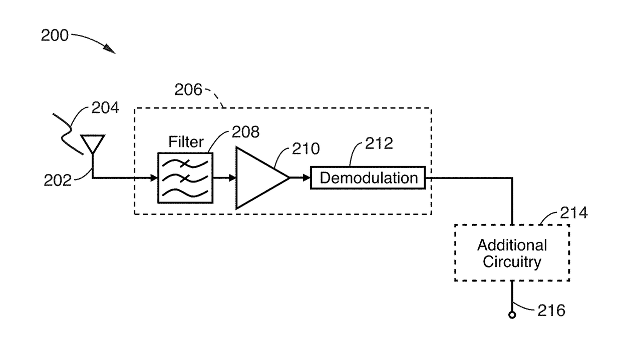
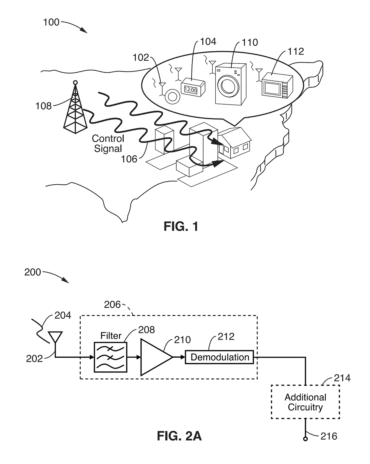
[0086]This disclosure describes a method and an apparatus for realizing a trigger sensor and transceiver based on a microelectromechanical resonant switch that can listen for valid inputs while in standby without the need for DC power consumption. This sensor / transceiver is unique in its use of a resonant switch (“resoswitch”) to receive an input, amplify it, demodulate it, and finally deliver power to a load. During this process, power is consumed only when a valid input signal within the passband of the resonant element actuates the structure with sufficient amplitude to cause switch impacting. This means zero quiescent power is needed, i.e., no power needed while listening in standby.

[0087]This device differs from conventional RFID tags in its much smaller power threshold needed to detect and receive a signal. In particular, a typical RFID tag requires enough power input to not only deliver the desired information, but also to power up its active circuits. This is norm...


PUM


Abstract

A microelectromechanical resonant switch (“resoswitch”) converts received radio frequency (RF) energy into an output signal with zero quiescent power usage by using a resonant element with a passband input sensitivity of: <−60 dBm, <−68 dBm, and <−100 dBm. The resoswitch first accepts incoming amplitude- or frequency-shift keyed RF energy at a carrier frequency, filters it, provides power gain via resonant impact switching, and finally envelop detects impact impulses to demodulate and recover the modulating waveform. Mechanical gain may be used to amplify received signals, whose amplitudes may be binned, thereby preserving use of amplitude modulated (AM) signals. A second resoswitch may be used to control additional circuitry, whereby the first resoswitch detects a control signal output to the additional circuitry.

Description

CROSS-REFERENCE TO RELATED APPLICATIONS[0001]This application claims priority to, and the benefit of, U.S. provisional patent application Ser. No. 62 / 351,893 filed on Jun. 17, 2016, incorporated herein by reference in its entirety. This application is also a 35 U.S.C. § 111(a) continuation-in-part of PCT international application number PCT / US2017 / 029769 filed on Apr. 27, 2017, incorporated herein by reference in its entirety, which claims priority to, and the benefit of, U.S. provisional patent application Ser. No. 62 / 333,182 filed on May 7, 2016, incorporated herein by reference in its entirety, and which also claims priority to, and the benefit of, U.S. provisional patent application Ser. No. 62 / 328,114 filed on Apr. 27, 2016, incorporated herein by reference in its entirety.STATEMENT REGARDING FEDERALLY SPONSORED RESEARCH OR DEVELOPMENT[0002]This invention was made with government support under Grant Number FA9550-10-1-0293 awarded by the Air Force Office of Scientific Research ...

Claims


Application Information

Patent Timeline
IPC IPC(8): H04L27/152H04B1/713H04L29/08H04W52/02H01H59/00
CPCH04L27/152H04B1/713H04L67/12H04W52/0229H01H59/0009H04L2027/0091H01H2001/0078H01H2059/0036Y02D30/70
Inventor NGUYEN, CLARK T.-C.LI, WEI-CHANGLIU, RUONAN
Owner RGT UNIV OF CALIFORNIA
Why Eureka
Try Eureka