Laminate, packaging bag, packaging bag with plug, and packaging bag with plug with hydrogenous-water

Active Publication Date: 2018-05-31
HOSOKAWA YOKO CO LTD
View PDF5 Cites 2 Cited by
  • Summary
  • Abstract
  • Description
  • Claims
  • Application Information

AI Technical Summary

Benefits of technology

[0033]According to the present invention, it is possible to provide a laminate having excellent gas barrier properties in which generation of bubbles is reliably suppressed without separately providing a surface protective layer or the like and a defect in the external a

Problems solved by technology

In this case, there is a possibility of deterioration in gas barrier properties due to the thin inorganic film peeling off.
However, in this case, the cost for providing the surface protective layer is required, and thus this case is not preferable.
In addition, in Patent Document 2, in a case in which the material of the plastic film is nylon, the effect cannot be obtained, and thus there is a problem of limiting the material of the plastic

Method used


Image

  • Laminate, packaging bag, packaging bag with plug, and packaging bag with plug with hydrogenous-water
  • Laminate, packaging bag, packaging bag with plug, and packaging bag with plug with hydrogenous-water
  • Laminate, packaging bag, packaging bag with plug, and packaging bag with plug with hydrogenous-water

Examples


example 1

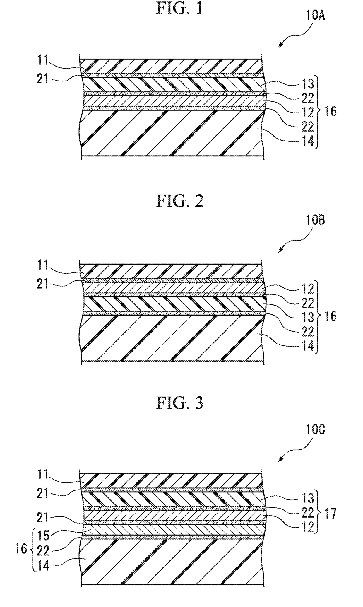
[0118]A laminate having the configuration in FIG. 1 was produced in the following manner.

[0119]First, a LLDPE film for forming the sealant layer 14, an aluminum foil for forming the second gas barrier layer 12, and a biaxially stretched polyamide film for forming the base layer 13 were laminated and bonded to one another by a dry lamination method using the adhesive (y) which is a two-component reaction polyurethane-based adhesive, and thus the member (a) 16 formed of the laminate having a film configuration of “sealant layer / adhesive layer (Y) (application amount: 3.5 g / m2) / second gas barrier layer / adhesive layer (Y) (application amount: 3.5 g / m2) / base layer” was produced.

[0120]The base layer 13 of the obtained member (a) 16 and the member (b) formed of a gas barrier transparent resin film for forming the first gas barrier layer 11 were bonded to each other by a dry lamination method using the adhesive (x) having a polyepoxy resin as a main ingredient and a polyamine resin as a cur...

example 2

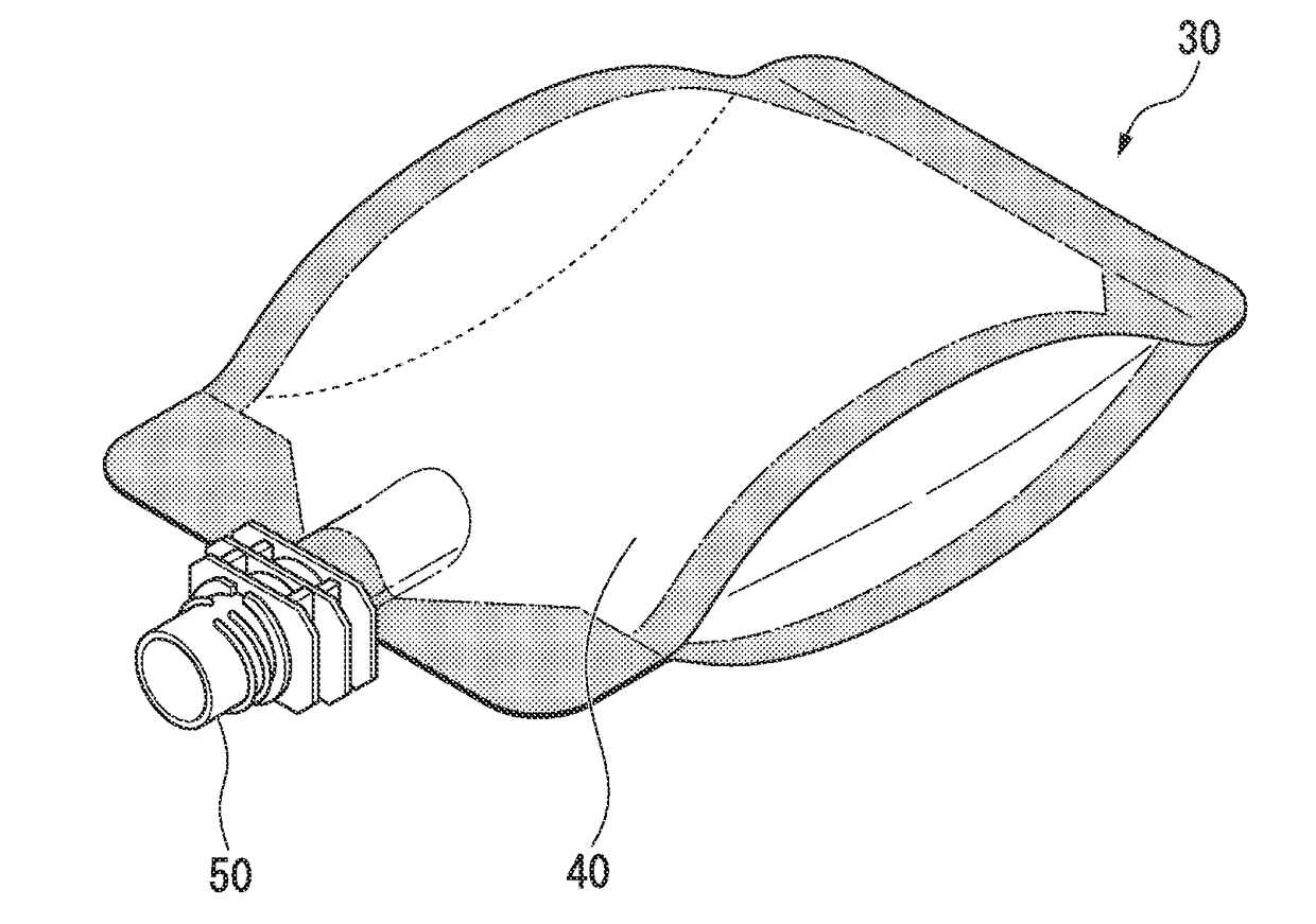
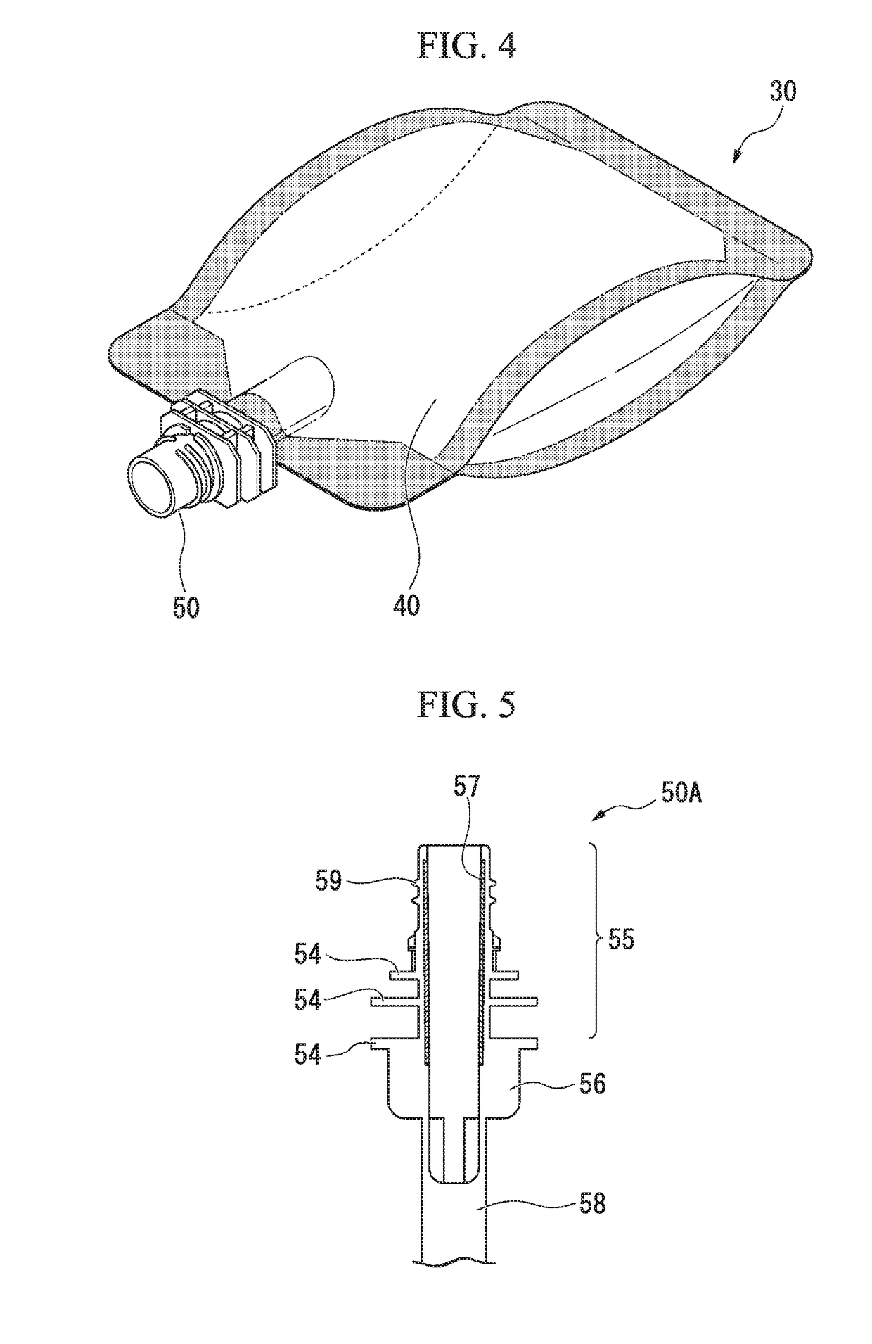
[0136]A hydrogenous water containing packaging bag with a plug was produced in the same manner as in Example 1 except that as the spout of the plug, a barrier cylinder around which an aluminum foil was wound was not integrally formed and a plug not having barrier properties was used and was evaluated in the same manner as in Example 1. The results are shown in Table 2.

example 3

[0137]A laminate having the configuration in FIG. 2 was produced using the material shown in Table 1 in the following manner.

[0138]First, an LLDPE film for forming the sealant layer 14, a biaxially stretched polyamide film for forming the base layer 13, and an aluminum foil for forming the second gas barrier layer 12 were bonded to one another by a dry lamination method using the adhesive (y) which is a two-component reaction polyurethane-based adhesive, and thus the member (a) 16 having a film structure of “sealant layer / adhesive layer (Y) (application amount: 3.5 g / m2) / base layer / adhesive layer (Y) (application amount: 3.5 g / m2) / second gas barrier layer” was produced.

[0139]Then, the second gas barrier layer 12 of the obtained member (a) 16 and the member (b) formed of a gas barrier transparent resin film for forming the first gas barrier layer 11 were bonded to each other by a dry lamination method using the adhesive (x) having a polyepoxy resin as a main ingredient and a polyamin...


PUM

PropertyMeasurementUnit
Transparencyaaaaaaaaaa

Abstract

The present invention provides a laminate (10A) having a first gas barrier layer (11) formed of a gas barrier transparent resin film and a second gas barrier layer (12) formed of a metal foil, in which at least one adhesive layer (X) (21) formed of an adhesive (x) including a polyepoxy resin as a main ingredient and a polyamine resin as a curing agent is provided between the first gas barrier layer (11) and the second gas barrier layer (12).

Description

TECHNICAL FIELD[0001]The present invention relates to a laminate suitably used for producing a packaging bag, a packaging bag using the laminate, a packaging bag with a plug formed by attaching a plug to the packaging bag, and a hydrogenous water containing packaging bag with a plug formed by filling the packaging bag with a plug with hydrogenous water.[0002]Priority is claimed on Japanese Patent Application No. 2015-132693, filed on Jul. 1, 2015, the content of which is incorporated herein by reference.BACKGROUND ART[0003]As packaging materials for packaging foods, industrial products and the like, laminates provided with a gas barrier layer to prevent permeation of gas have been widely used. Among these, in applications that require particularly high gas barrier properties, two gas barrier layers are provided in a laminate in some cases.[0004]For example, Patent Document 1 discloses a packaging material in which a layer of an inorganic compound vapor deposition film on which a thi...

Claims


Application Information

Patent Timeline
IPC IPC(8): B32B7/12B32B15/08B65D75/58B65D65/40A23L2/54C09J163/00C09J175/04
CPCB32B7/12B32B15/08B65D75/5883B65D65/40A23L2/54C09J163/00C09J175/04B32B2439/46B32B2307/412B65D2565/387B65D2575/586A23V2002/00B32B2307/7242B32B2439/70B32B3/08B32B7/04B32B15/082B32B15/085B32B15/088B32B15/09B32B15/20B32B27/08B32B27/304B32B27/306B32B27/32B32B27/34B32B27/36B32B27/365B32B2250/04B32B2255/10B32B2255/20B32B2270/00B32B2307/306B32B2307/31B32B2307/518B32B2307/546B32B2307/554B32B2307/558B32B2307/714B32B2307/7244B32B2307/732B32B2307/748C09J11/06B32B27/00B65D75/58
Inventor SATO, SYOTAARAI, HIROYUKIKAGAWA, TOMOYA
Owner HOSOKAWA YOKO CO LTD
Why Eureka
Try Eureka