
Rotor state feedback system

Inactive Publication Date: 2018-05-31
SIKORSKY AIRCRAFT CORP
View PDF11 Cites 15 Cited by
  • Summary
  • Abstract
  • Description
  • Claims
  • Application Information

AI Technical Summary

Benefits of technology

The patent describes a control system for a rotorcraft that uses optical sensors to measure the movement of the rotor blades and an algorithm to calculate the strain on the blades. This information is then used to control the pitch of the blades, elevator, and other components of the rotor. The system can also include a servo control system to adjust the blade pitching and elevator pitching. The technical effect of this system is to improve the performance and efficiency of rotorcraft by optimizing the control of the rotor blades.

Problems solved by technology

However, since these control laws may not include rotor state information, they are often designed conservatively to ensure the avoidance of critical tip clearance and load constraints while trading on maneuverability and performance attributes.

Method used


Image

  • Rotor state feedback system
  • Rotor state feedback system
  • Rotor state feedback system

Examples


Embodiment Construction

[0028]As will be described below, a set of fiber optic sensors (e.g. fiber Bragg sensors, Fabry-Perot interferometer sensors or Rayleigh backscatter sensors) and state estimation models can be used to estimate the rotor states of aircraft rotor blades. When a force is applied to one of the blades, e.g. during maneuvering flight, the fiber optic sensors provide an optical response that is converted to information reflective of the rotor feedback states through the use of the state estimation models. This information is used in the flight control computer to generate a suitable main rotor servo and elevator command to attenuate high loads in the rotor system, to accommodate a less conservative rotor design, or, alternatively, allow for a larger operational envelope.

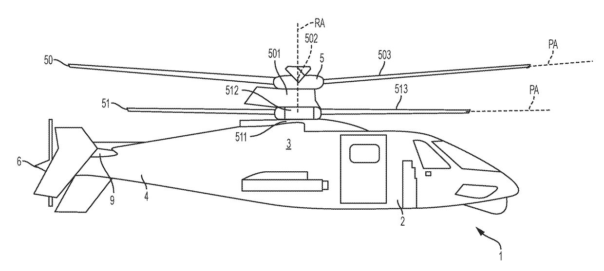
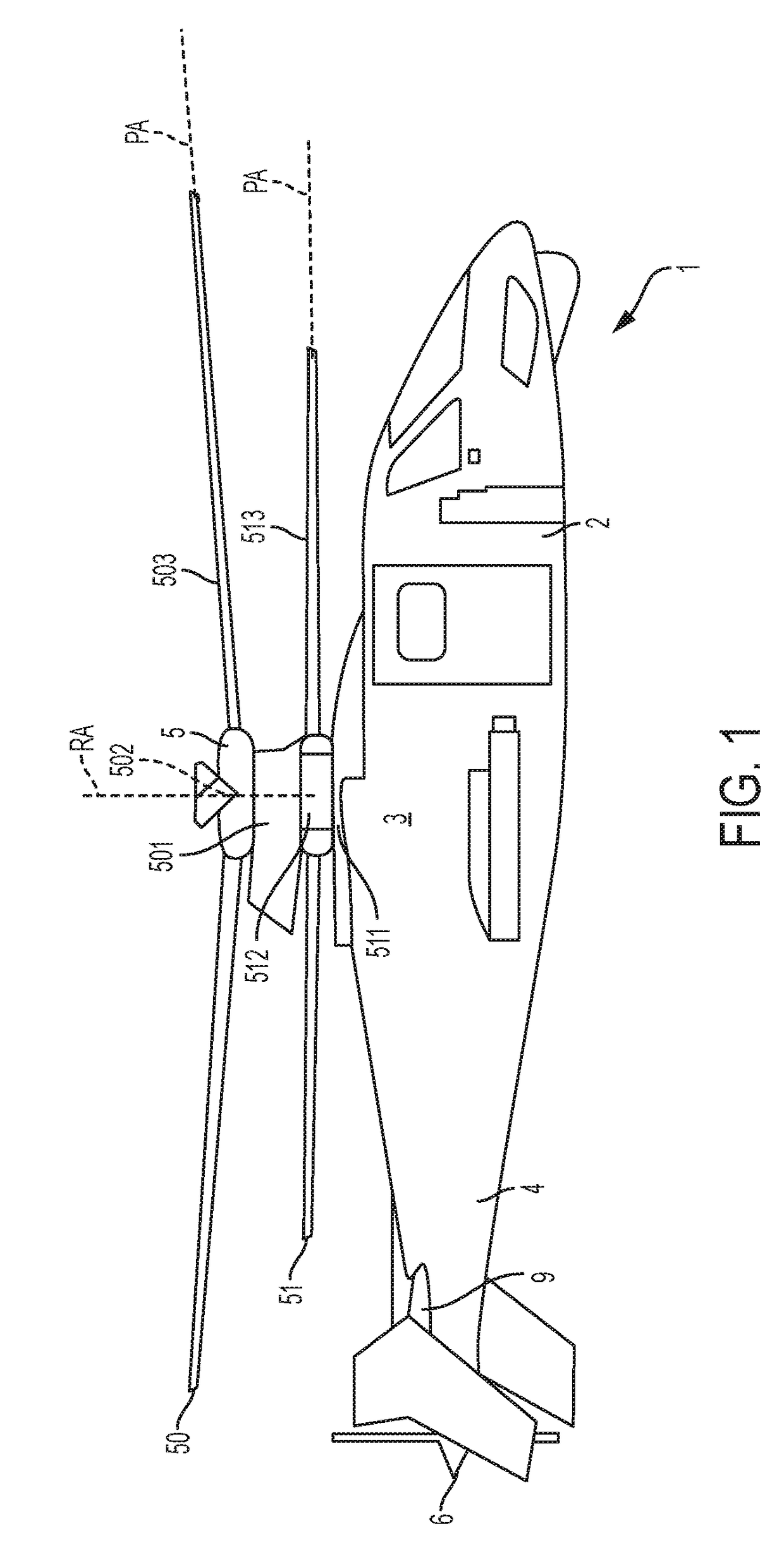
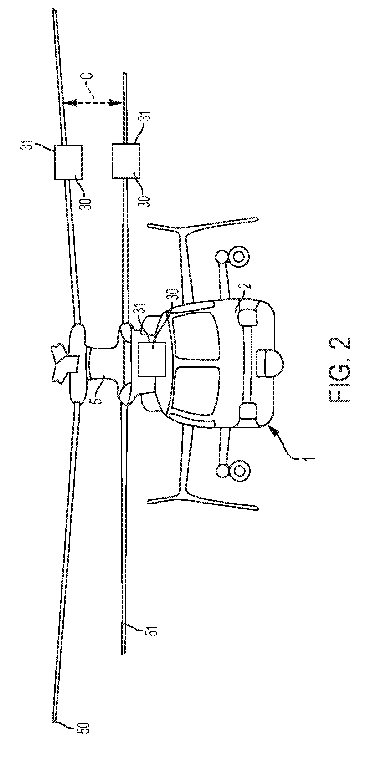
[0029]With reference to FIGS. 1-3, a coaxial rotorcraft 1 is provided and may be configured for example as a coaxial, counter-rotating helicopter or some other fixed or variable wing aircraft with single or multiple rotors....


PUM


Abstract

A control system is provided and includes a servo control system configured to control aerodynamic element pitching, an optical sensor system disposed along rotor blades to generate an optical response reflective of rotor feedback states of the rotor blades and a processing unit operably coupled between the servo control and optical sensor systems, the processing unit being configured to calculate strain in the rotor blades from the optical response, convert the calculated strain into readings of the rotor feedback states and issue a servo command to the servo control system as an instruction for controlling the aerodynamic element pitching.

Description

FEDERAL RESEARCH STATEMENT[0001]The following embodiments and aspects were made with government support under the W911W6-13-2-0013 Innovative Rotors and Vehicle Management System Technologies contract awarded by the Army. The government has certain rights in the embodiments and aspects.BACKGROUND[0002]The subject matter disclosed herein relates to a rotor state feedback system and, more particularly, to a rotor state feedback system utilizing optical sensors for coaxial rotors.[0003]A coaxial aircraft, such as a coaxial, counter-rotating helicopter, has an airframe that has a top portion and a tail portion extending in the aft direction. The aircraft further includes a main rotor assembly at the top portion and an auxiliary propulsor at the tail portion. Also in the tail portion is an elevator. When driven to rotate by an engine supported within or on the airframe via a transmission, the main rotor assembly, which includes coaxial, counter-rotating rotors, generates lift for the air...

Claims


Application Information

Patent Timeline
Patent Type & Authority Applications(United States)
IPC IPC(8): B64C27/00B64C27/10G05D1/00G05D1/08
CPCB64C27/008B64C27/10G05D1/0066G05D1/0858B64C2027/8236B64C2027/8272
Inventor GEIGER, DEREKKIM, SEUNG BUMWULFF, OLEKELLNER, AARONMORRIS, BRIAN EDWARD
Owner SIKORSKY AIRCRAFT CORP
Learn More