
Roll to roll fabrication apparatus for preventing thermal impact

Active Publication Date: 2018-05-31
LG DISPLAY CO LTD
View PDF7 Cites 0 Cited by
  • Summary
  • Abstract
  • Description
  • Claims
  • Application Information

AI Technical Summary

Benefits of technology

This patent describes a method to prevent wrinkle formation on a film during a high-temperature process, by gradually increasing the temperature of the film while winding it on a heated drum. This reduces the impact of the heat on the film. Additionally, the patent also describes a vacuum system that prevents mixing of gases during the process, resulting in a better quality film.

Problems solved by technology

However, the conventional method to fabricate such a flexible display device has the following problems.
However, in case of attaching a plastic substrate onto a glass mother substrate, the expensive glass substrate of a large area is required.
This may cause fabrication costs to be increased, and equipment and processes to be additionally required since the plastic substrate and the glass substrate should be attached to each other and then separated from each other.
As a result, entire fabrication costs are increased.
As a result, a consecutive inline process cannot be performed.

Method used


Image

  • Roll to roll fabrication apparatus for preventing thermal impact
  • Roll to roll fabrication apparatus for preventing thermal impact
  • Roll to roll fabrication apparatus for preventing thermal impact

Examples


first embodiment

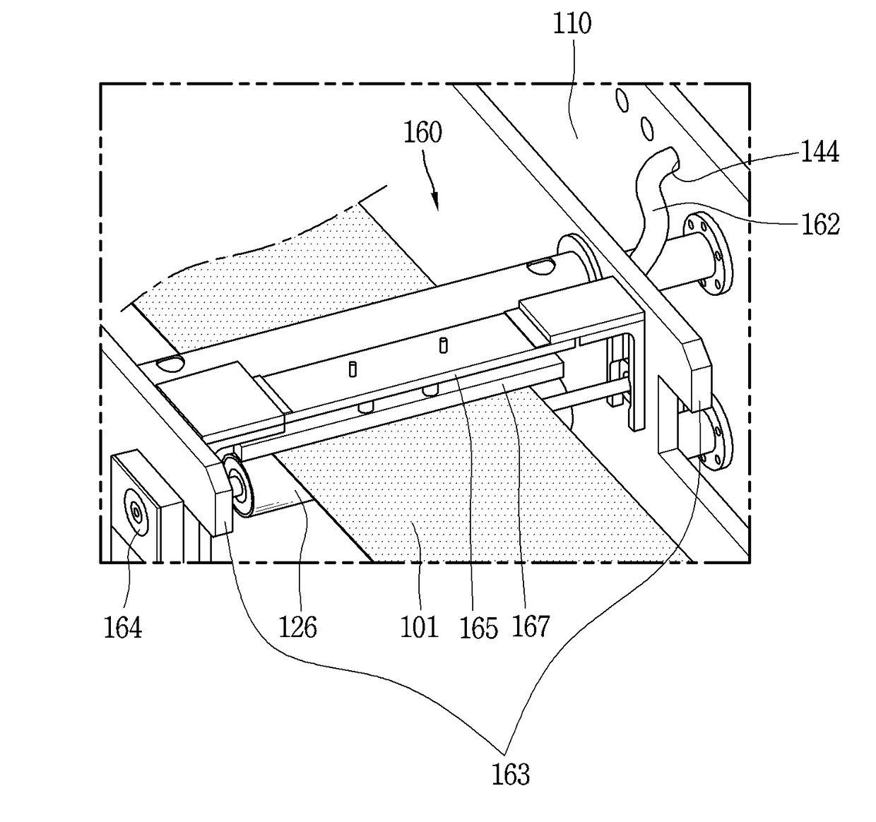
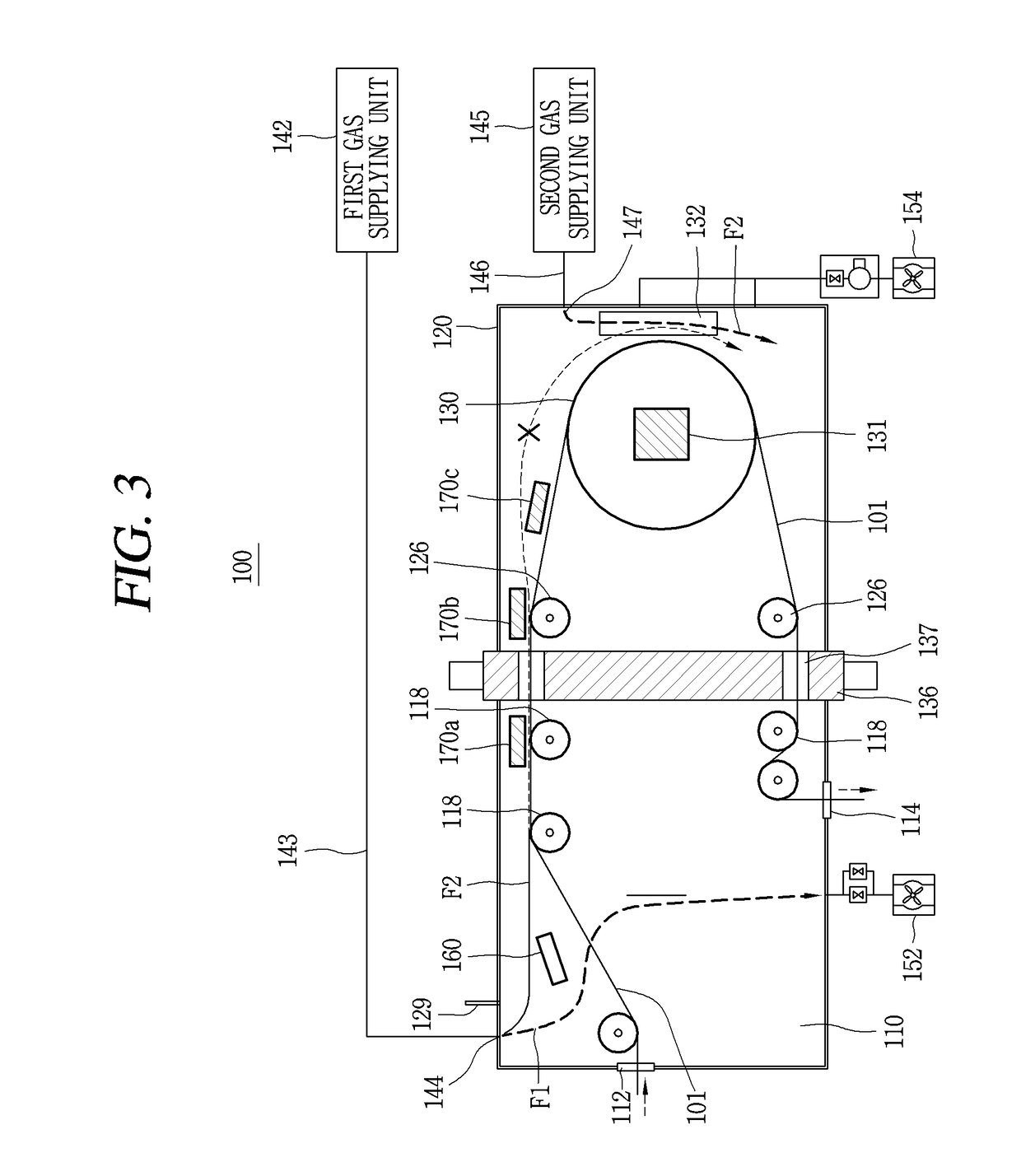
[0041]FIG. 3 is a view showing the roll to roll fabrication apparatus 100 according to the present disclosure. The roll to roll fabrication apparatus 100 shown in FIG. 3 represents the roll to roll fabrication apparatus 100 for a CVD process. However, the roll to roll fabrication apparatus 100 for a CVD process is similar to a roll to roll fabrication apparatus 100 for other processes. Accordingly, the present disclosure will be explained by taking the roll to roll fabrication apparatus 100 for a CVD process as a representative example.

[0042]As shown in FIG. 3, the roll to roll fabrication apparatus 100 performs its function within a vacuum chamber. The vacuum chamber includes an installation chamber 110 where a film 101 is transferred from a previous process region and is transferred to another process region, and a process chamber 120 where a corresponding process is performed on the film.

[0043]The installation chamber 110 includes an inlet 112 where the film 101 processed in a pr...

second embodiment

[0092]FIG. 7 is a view showing a roll to roll fabrication apparatus according to the present disclosure. The roll to roll fabrication apparatus according to this embodiment is similar to that shown in FIG. 3. In the roll to roll fabrication apparatus shown in FIG. 3, all processes are consecutive inline roll to roll processes, and each of the roll to roll processes is connected to a previous process and a next process. Namely, in the apparatus as shown in FIG. 3, the film 101 was previously on a different roll and was involved in a different process, which was a separate roll to roll fabrication process using a different roll to roll fabrication apparatus.

[0093]On the other hand, the roll to roll fabrication apparatus according to the embodiment of FIG. 7 is a roll to roll process which is disconnected from a previous process and a next process.

[0094]The roll to roll fabrication apparatus according to the embodiment of FIG. 7 has the same basic structure as the roll to roll fabricat...


PUM

PropertyMeasurementUnit
Timeaaaaaaaaaa
Temperatureaaaaaaaaaa
Timeaaaaaaaaaa

Abstract

A roll to roll fabrication apparatus includes: a vacuum chamber having an installation chamber and a process chamber; a preprocessing unit in the installation chamber to process a surface of a film which is transferred to enhance a film characteristic in a subsequent CVD process; a process drum in the process chamber to wind the film thereon; a process treatment unit in the process chamber to form a layer by performing a CVD process on the film wound on the process drum; and a plurality of heaters in the installation chamber and the process chamber to gradually increase a temperature of the film wound on the process drum to prevent application of a thermal impact to the film due to the high-temperature process drum.

Description

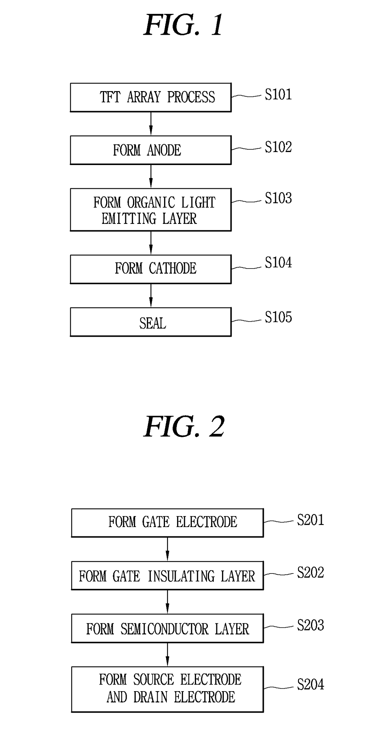
CROSS-REFERENCE TO RELATED APPLICATION[0001]Pursuant to 35 U.S.C. § 119(a), this application claims the benefit of an earlier filing date of and the right of priority to Korean Application No. 10-2016-0159702, filed on Nov. 28, 2016, the contents of which are incorporated by reference herein in its entirety.BACKGROUNDTechnical Field[0002]This specification relates to a roll to roll fabrication apparatus capable of performing processes rapidly and consecutively, and capable of preventing a thermal impact from being applied to a ductile substrate.Description of the Related Art[0003]Recently, a flexible display device using a ductile substrate such as a plastic substrate is being developed for enhanced portability and convenience. Such a flexible display device is fabricated in a following manner. Firstly, a substrate formed of a plastic material such as polyimide is attached onto a mother substrate formed of glass. Then, a plurality of display panels are formed on the mother substrate...

Claims


Application Information

Patent Timeline
IPC IPC(8): C23C16/54H01J37/32H01L27/12C23C16/46
CPCC23C16/545H01J37/3277H01L27/1262C23C16/46H01J2237/2065H01J2237/3321H01J2237/3328H01L27/3262H10K71/164H10K71/40C23C16/0245H01L31/206C23C16/56C23C16/01H01L2224/95115H01L21/02658H10K71/00H10K59/1213
Inventor YOUK, SEUNGHYUNKOOK, YUNHOCHOI, SUNGWOO
Owner LG DISPLAY CO LTD
Learn More