Eureka AIR delivers breakthrough ideas for toughest innovation challenges, trusted by R&D personnel around the world.

Shift control system for vehicle

a technology for controlling systems and vehicles, applied in the direction of electric control, ignition automatic control, machines/engines, etc., can solve the problems of significant response delay, shift shock, and deviation between actual output torque and target torque, so as to achieve the effect of not wasting fuel

Inactive Publication Date: 2018-05-31
TOYOTA JIDOSHA KK
View PDF0 Cites 5 Cited by
  • Summary
  • Abstract
  • Description
  • Claims
  • Application Information

AI Technical Summary

Benefits of technology

The patent relates to a system for controlling shifting in a vehicle. The system calculates an integrated value to compensate for a delay in torque-down control and uses it to correct the target torque during shifting to synchronize engine speed with the target speed at the end of the shifting operation. This reduces the shift shock experienced during gear shifts and ensures that fuel is not wasted.

Problems solved by technology

In this situation, if the engine speed is changed abruptly, a shift shock may be caused.
However, such torque-down control based on the air intake may cause a significant response delay.
Either control is, however, designed to change an engine output torque indirectly by changing the amount of air / fuel mixture and combustion state, and hence deviation between an actual output torque and a target torque may be caused inevitably.
For this reason, owing to control variations, response delays or the like, the deviation between a target torque and an actual torque in torque-down control may also occur at the end of shifting operation.
Consequently, the engine speed may be changed significantly to be synchronized at the end of shifting operation to cause a shift shock.

Method used


Image

  • Shift control system for vehicle
  • Shift control system for vehicle
  • Shift control system for vehicle

Examples


Embodiment Construction

)

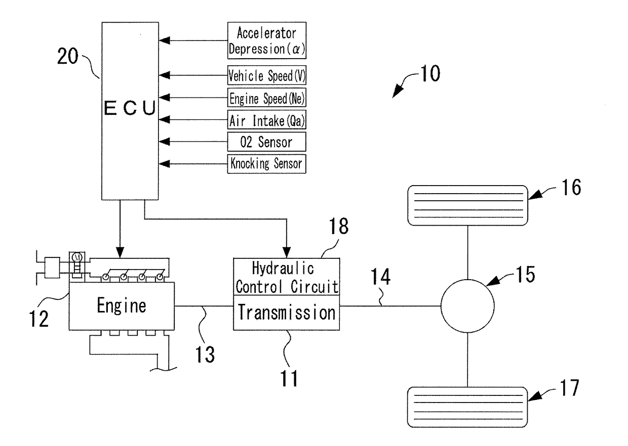
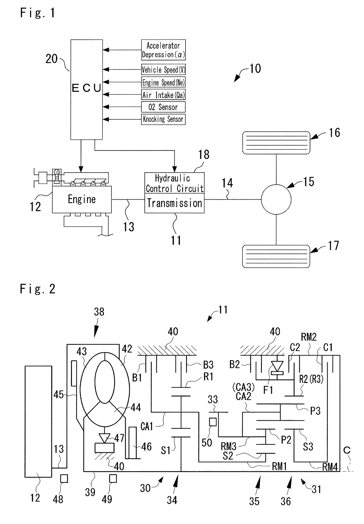
[0038]FIG. 1 is a block diagram schematically showing an example of a vehicle to which the control system according to at least one embodiment of the present disclosure. As shown in FIG. 1, a vehicle 10 includes an automatic transmission (as will be simply caller the “transmission” hereinafter) 11 that performs a clutch-to-clutch shifting. The transmission 11 is connected to an output side of an engine 12. Driving force generated by the engine 12 is transmitted to an input shaft 13 of the transmission 11. An output shaft 14 of the transmission 11 transmits the driving force to left and right drive wheels 16 and 17 through a differential gear unit 15 as a final reduction gear unit. The engine 12 includes a gasoline engine and a diesel engine. Note that the vehicle according to an embodiment of the present application may include a hybrid vehicle in which a prime mover includes an engine and a motor. Specifically, the control system according to the embodiment may be applied to a veh...


PUM


Abstract

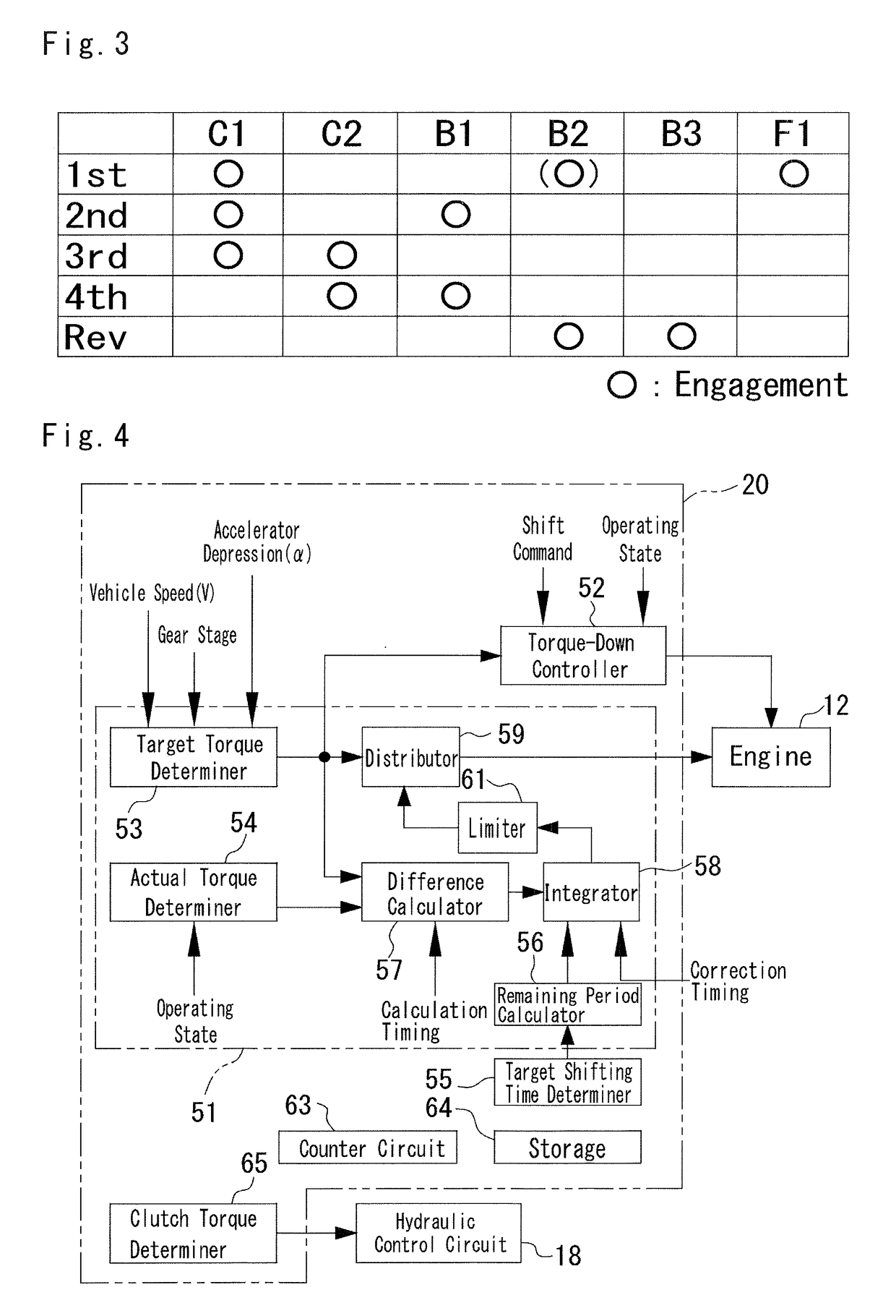
A shift control system which can reduce a shift shock is provided. A target torque determiner set a target torque of an engine based on an accelerator position. An actual torque determiner calculates an actual torque of the engine in the inertia phase. A controller calculates an integrated value of a difference between the target torque and the actual torque from a commencement of the inertia phase to a predetermined time point before a termination of the inertia phase, and corrects the target torque in a remaining period between the predetermined time point and the termination of the inertia phase.

Description

CROSS REFERENCE TO RELATED APPLICATION[0001]The present invention claims the benefit of Japanese Patent Application No. 2016-232742 filed on Nov. 30, 2016 with the Japanese Patent Office, the disclosures of which are incorporated herein by reference in its entirety.BACKGROUNDField of the Invention[0002]Embodiments of the present disclosure relate to a shift control system for vehicle including an automatic transmission in which a gear stage is shifted by manipulating engagement devices such as clutches and brakes.Discussion of the Related Art[0003]A shift control system for a vehicle executes a shifting operation of a gear stage to adjust an engine speed in accordance with the traveling state of the vehicle when a driver depresses the accelerator pedal or the vehicle speed increases. For example, when the driver depresses the accelerator pedal to execute upshifting to the high speed stage, the shift control system disengages an engagement device in engagement in a low speed stage be...

Claims


Application Information

Patent Timeline
IPC IPC(8): F02D41/02B60W30/19F02D37/02F16H63/50
CPCF02D41/023B60W30/19F02D37/02F16H63/502F02D2250/18F16H2059/363F16H2061/0216F02D29/02F02D41/0002F02D41/1401F02D2041/001F02D2200/1002F02D2200/60F02P5/045F02P5/15F02P5/152B60W10/02B60W10/06B60W10/10B60W30/184B60W2510/1005B60W2520/10B60W2540/10F02D11/105F02D41/123F02D2400/12F16H61/0403
Inventor WATANABE, HIROSHIEIRAKU, AKIRA
Owner TOYOTA JIDOSHA KK
Why Eureka
Eureka Blog
Learn More