A turbomachinery gasket and a turbomachinery provided with said gasket

a technology for turbomachinery and gaskets, which is applied in the direction of leakage prevention, liquid fuel engines, non-positive displacement pumps, etc., can solve the problems of difficult repositioning, difficult to heat up the gasket to the correct temperature in order to remove, and already difficult operation, etc., to achieve easy and quick installation

Active Publication Date: 2018-05-31
NUOVO PIGNONE TECH SRL
View PDF1 Cites 0 Cited by
  • Summary
  • Abstract
  • Description
  • Claims
  • Application Information

AI Technical Summary

Benefits of technology

[0011]Therefore, there is a general need to provide a turbomachinery gasket that may be easily and quickly installed even on the tubular assembly of a large turbomachinery.
[0013]Moreover, there is a need to provide a turbomachinery gasket that can be installed on the tubular assembly avoiding the risk of severe burnings to the operators.

Problems solved by technology

The operation, that is already not easy, is complicated by the fact the temperature of the gasket is around 100° C. This requires the operators to wear suitable protections, in order to avoid severe burnings to the skin.
In fact, if the gasket temperature falls below a certain limit, while it is not yet in the correct position, it may remain blocked on the tubular assembly due to its diameter reduction, and it may be difficult to re-position it.
It is also to be noted that, in the prior art, once the gasket is positioned in the groove, it is very difficult to heat it up to the correct temperature in order to remove it.
Therefore, most of the times, an installed gasket need to be destroyed and it cannot be re-used.

Method used


Image

  • A turbomachinery gasket and a turbomachinery provided with said gasket
  • A turbomachinery gasket and a turbomachinery provided with said gasket
  • A turbomachinery gasket and a turbomachinery provided with said gasket

Examples


Embodiment Construction

[0030]The following description of exemplary embodiments refers to the accompanying drawings.

[0031]The following description does not limit the invention. Instead, the scope of in an embodiment defined by the appended claims.

[0032]Reference throughout the specification to “one embodiment” or “an embodiment” means that a particular feature, structure, or characteristic described in connection with an embodiment is included in at least one embodiment of the subject matter disclosed. Thus, the appearance of the phrases “in one embodiment” or “in an embodiment” in various places throughout the specification is not necessarily referring to the same embodiment. Further, the particular features, structures or characteristics may be combined in any suitable manner in one or more embodiments.

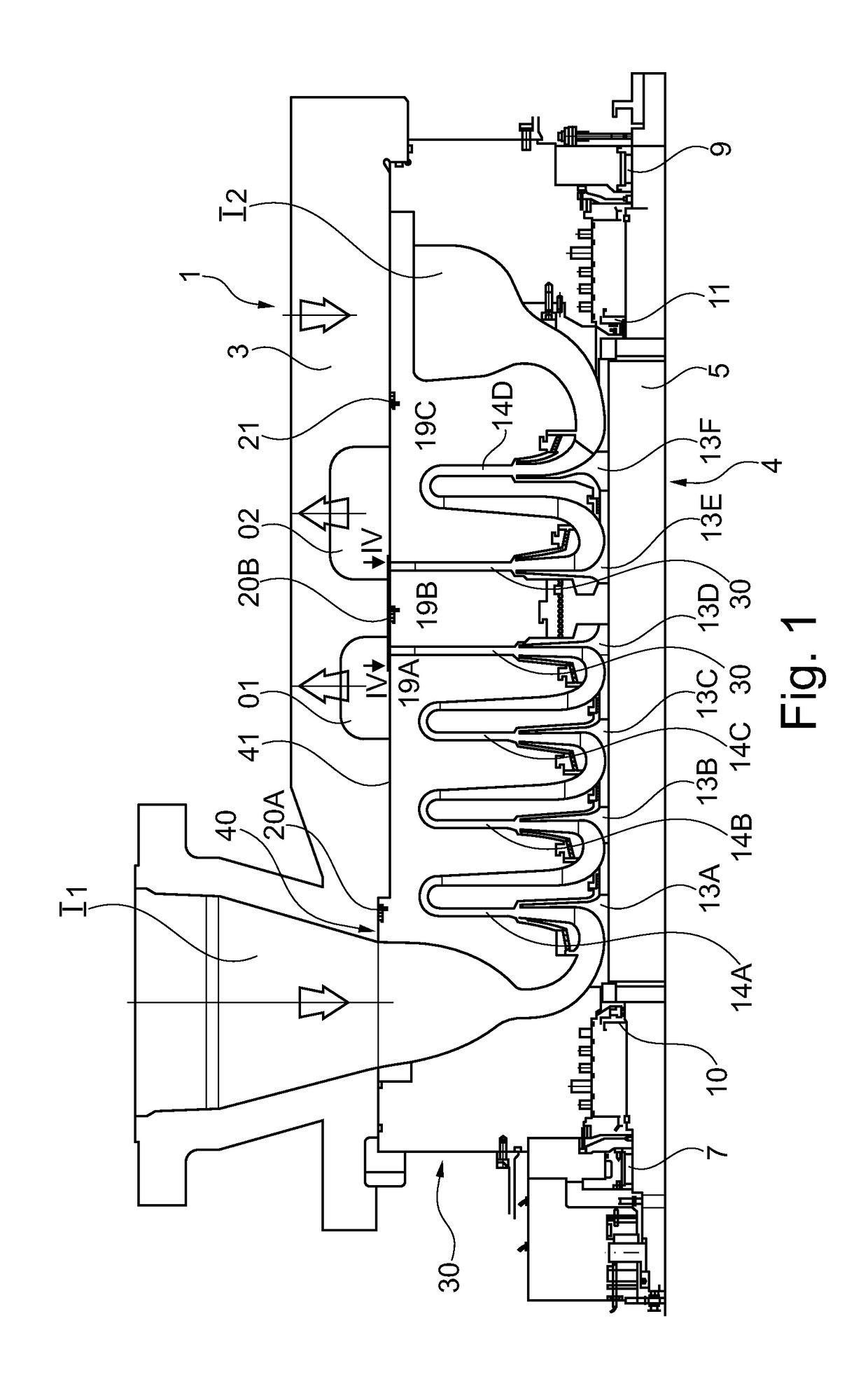
[0033]FIG. 1 illustrates a simplified sectional view (where section lines are omitted), of a turbomachinery, in particular a multistage centrifugal compressor 1 according to the present disclosure. The m...


PUM

PropertyMeasurementUnit
lengthaaaaaaaaaa
lengthaaaaaaaaaa
temperatureaaaaaaaaaa

Abstract

A turbomachinery gasket comprising at least a first curved elongated element having a coupling part configured to cooperate with a tubular assembly in order to keep the gasket in position on the tubular assembly, and an outer surface configured to seal against an outer casing provided to house the tubular assembly, the first curved elongated element comprising a first and a second free end, the first free end providing a first protruding lip and the second free end providing a second protruding lip, the first protruding lip being configured to overlap with the second protruding lip of the first curved elongated element or with a second protruding lip of a second elongated element functionally identical to the first one, so that, when the gasket is in use, a seal in that part of the gasket having said protruding lips is granted.

Description

FIELD OF INVENTION[0001]Embodiments of the subject matter disclosed herein correspond to turbomachinery gaskets, and to a turbomachinery, in particular a compressor, comprising said gasket.BACKGROUND OF THE INVENTION[0002]In the turbomachinery field, gaskets are used to separate zones operating at different pressures. A gasket may be located between a tubular assembly, which may be a compressor bundle formed by one or more diaphragms and a rotor, and an outer casing.[0003]In the prior art, at least an annular groove is provided on the tubular assembly outer surface to house a closed-ring gasket, usually realized in a Teflon (PTFE) based material. In order to fit the gasket in the annular grove, the first step is to heat-up the closed-ring gasket to temporary increase its diameter. The increase of the gasket diameter makes it possible to fit it onto the tubular assembly and make the gasket slide up to the groove. When the gasket temperature decreases, its diameter reduces accordingly...

Claims


Application Information

Patent Timeline
Patent Type & Authority Applications(United States)
IPC IPC(8): F04D29/08F04D29/42F16J15/08
CPCF04D29/083F04D29/4206F16J15/0818F04D17/12F04D29/286F04D29/441F01D11/003F01D11/005F04D17/122F04D29/624F05D2240/55F05D2250/75F05D2300/432
Inventor SARRI, FRANCOBERNOCCHI, ANDREASMORTI, FRANCO
Owner NUOVO PIGNONE TECH SRL
Why Eureka
Try Eureka