Display Device and Operating Method Thereof

a display device and operating method technology, applied in the field of display devices, can solve the problems of noise influence and deterioration of the sensing accuracy of the touch sensor unit, and achieve the effects of smooth input, high sensing accuracy of the touch sensor unit, and smooth inpu

Active Publication Date: 2018-05-31
SEMICON ENERGY LAB CO LTD
View PDF10 Cites 11 Cited by
  • Summary
  • Abstract
  • Description
  • Claims
  • Application Information

AI Technical Summary

Benefits of technology

[0017]One embodiment of the present invention can provide a novel display device. Another embodiment of the present invention can provide a display device that achieves both high sensing accuracy of a touch sensor unit and smooth input using the touch sensor unit. Another embodiment of the present invention can provide a display device that achieves both high sensing accuracy of a touch sensor unit and smooth input using the touch sensor unit with a small number of signals. Another embodiment of the present invention can provide a display device with low power consumption.
[0018]Another embodiment of the present invention can provide a novel driving method that achieves both high sensing accuracy of a touch sensor unit and smooth input using the touch sensor unit. Another embodiment of the present invention can provide an electronic device including the novel display device.

Problems solved by technology

In the case where the touch sensor unit performs sensing operation at the time when the display unit rewrites a display image, the sensing accuracy of the touch sensor unit deteriorates by the influence of noise.

Method used


Image

  • Display Device and Operating Method Thereof
  • Display Device and Operating Method Thereof
  • Display Device and Operating Method Thereof

Examples


embodiment 1

[0075]In this embodiment, a display device including a display unit and a touch sensor unit is described. In particular, a gate driver included in the display unit and a relationship between display image rewriting by the display unit and sensing operation (touch sensing) by the touch sensor unit are described.

>

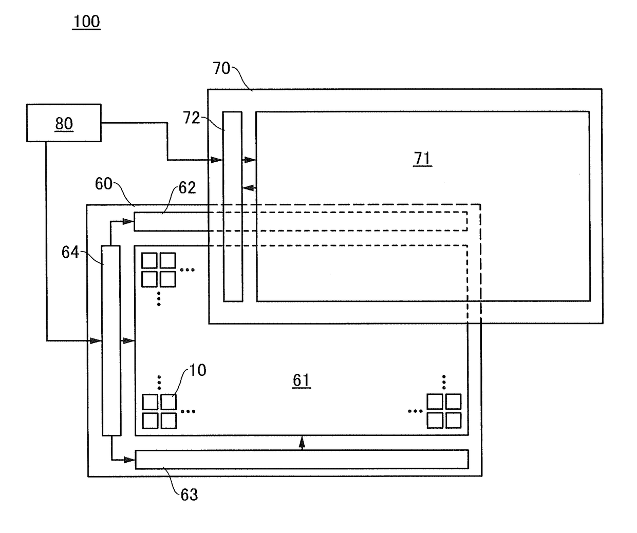
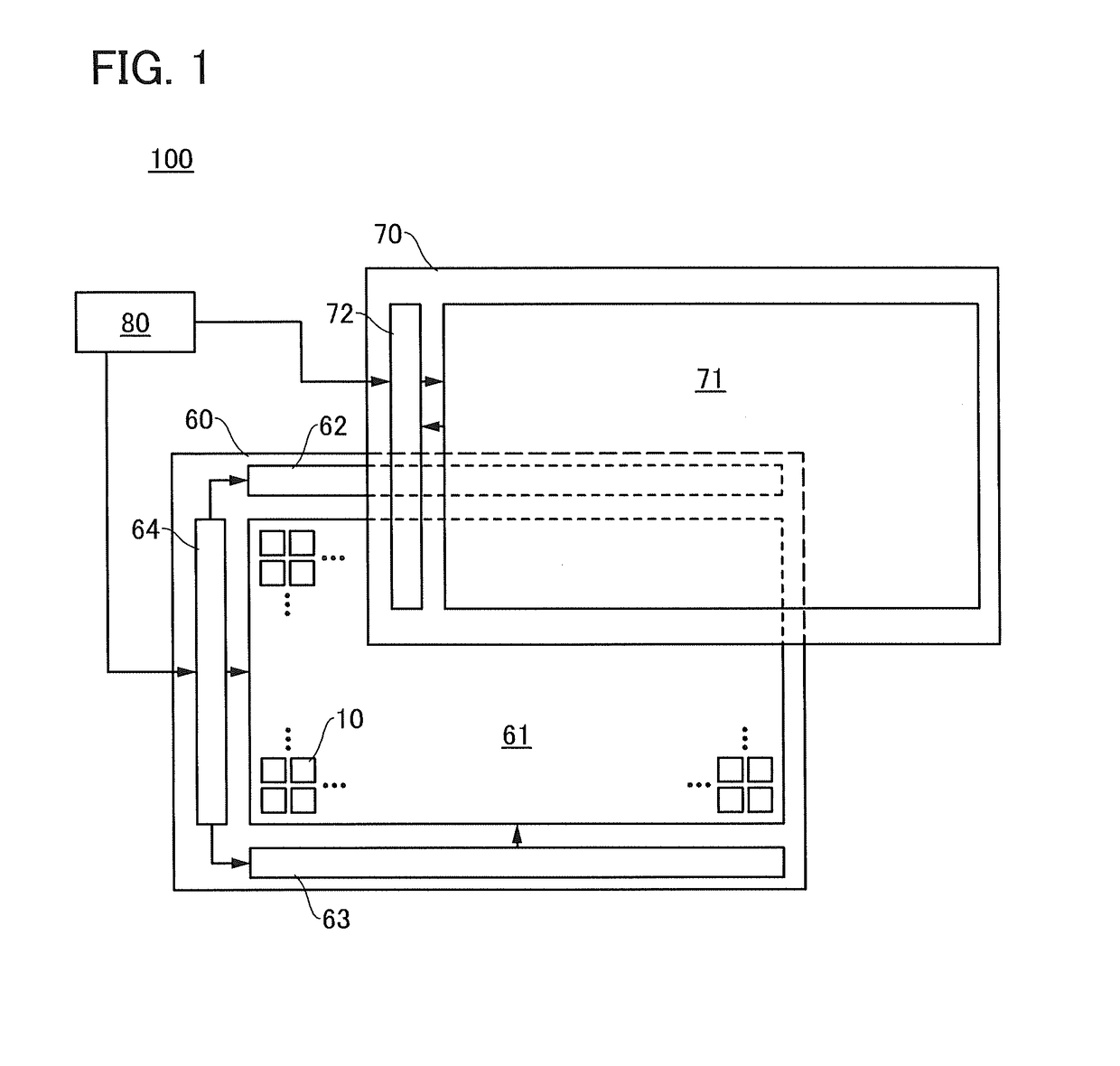
[0076]FIG. 1 is a block diagram illustrating a structure example of a display device. A display device 100 includes a display unit 60, a touch sensor unit 70, and an application processor 80.

[0077]The display unit 60 includes a pixel array 61, a gate driver 62, a gate driver 63, and a source driver IC 64.

[0078]The pixel array 61 includes a plurality of pixels 10. Each of the pixels 10 is an active element driven by a transistor. The pixel array 61 has a function of forming a display region of the display unit 60 and displaying an image. A more specific structure example of the pixel array 61 is described in Embodiment 4.

[0079]The gate driver 62 and the gate driver 63 (hereina...

embodiment 2

[0175]In this embodiment, a structure example of the touch sensor unit 70 mentioned in the above embodiment is described with reference to FIGS. 23A to 23C and FIGS. 24A and 24B.

[0176]A specific structure example of the touch sensor unit 70 is described with reference to FIGS. 23A to 23C and FIGS. 24A and 24B.

[0177]FIG. 23A is a top view of the touch sensor unit 70. FIGS. 23B and 23C are each a projection view illustrating part of FIG. 23A.

[0178]FIG. 24A is a top view of a portion in which a control line and a sensing signal line are adjacent to each other. FIG. 24B is a projection view that schematically illustrates an electric field generated in the adjoining portion.

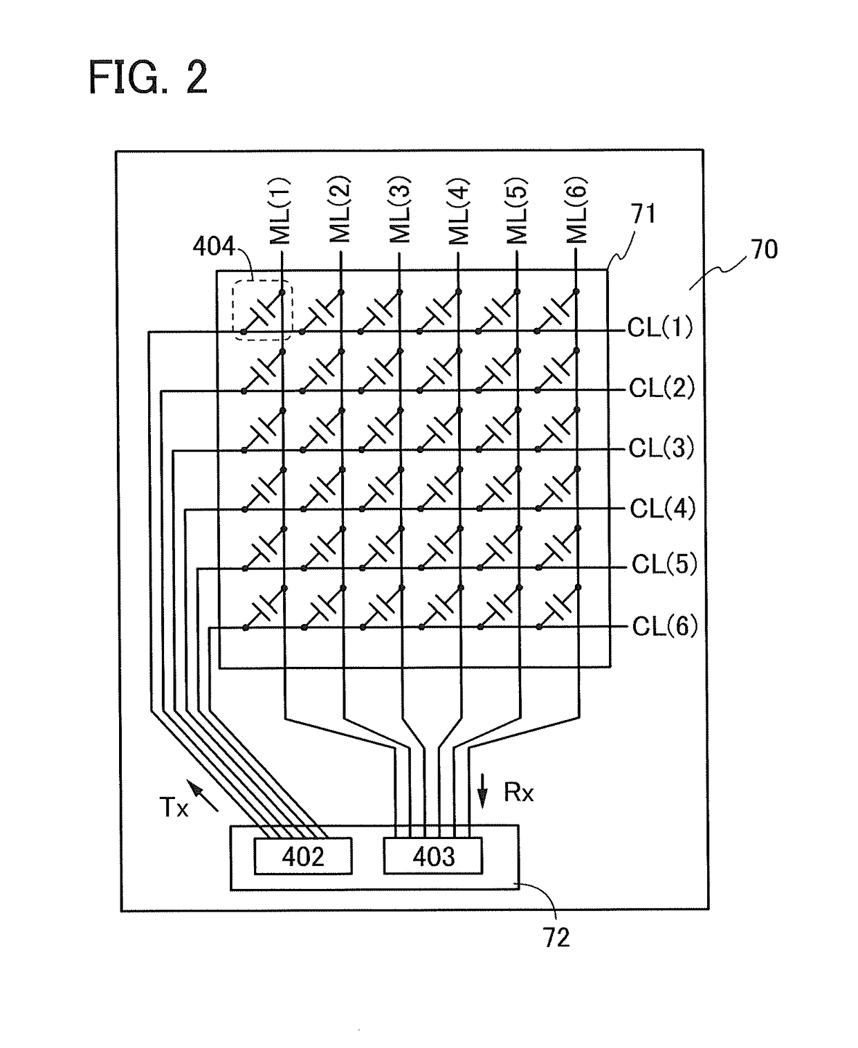
[0179]The touch sensor unit 70 includes the sensor array 71. The sensor array 71 includes a wiring CL(g), a wiring ML(h), and a conductive film (see FIG. 23A). Note that g and h are each an integer greater than or equal to 2.

[0180]For example, a conductive film divided into a plurality of regions can be used for the s...

embodiment 3

[0195]In this embodiment, a structure example of the source driver IC 64 mentioned in the above embodiment is described with reference to FIGS. 25A and 25B.

[0196]FIGS. 25A and 25B are block diagrams of the source driver IC 64 in the case where a hybrid element including a reflective element and a light-emitting element is used for the pixel 10.

[0197]The source driver IC 64 illustrated in FIG. 25A includes a control circuit 801, a driver 802, a frame memory 803, a frame memory 804, a gate driver signal generation circuit 806, and a gate driver signal generation circuit 807.

[0198]The control circuit 801 has a function of receiving a signal from the application processor 80 and transmitting the signal to each circuit included in the source driver IC 64. Examples of interface standards of the signal transmitted from the application processor 80 to the control circuit 801 include a mobile industry processor interface (MIPI) and a serial peripheral interface (SPI).

[0199]The driver 802 has...


PUM


Abstract

A display device that achieves both high-accuracy sensing by a touch sensor unit and smooth input using the touch sensor unit is provided. The display device includes a display unit and the touch sensor unit. The touch sensor unit performs touch sensing operation at a different timing from display image rewriting by the display unit, whereby the high-accuracy sensing can be achieved. The display unit has a function of rewriting a display image only in a region that needs to be rewritten. In the case where the entire display region is not necessarily rewritten, the time for the sensing operation by the touch sensor unit can be lengthened, whereby the smooth input can be achieved.

Description

BACKGROUND OF THE INVENTION1. Field of the Invention[0001]One embodiment of the present invention relates to a display device and a method for operating the display device. Furthermore, one embodiment of the present invention relates to a semiconductor device.[0002]Note that one embodiment of the present invention is not limited to the above technical field. The technical field of the invention disclosed in this specification and the like relates to an object, a method, or a manufacturing method. Furthermore, one embodiment of the present invention relates to a process, a machine, manufacture, or a composition of matter.[0003]Specifically, examples of the technical field of one embodiment of the present invention disclosed in this specification and the like include a display device, a semiconductor device, an electronic device, a method for driving any of them, and a method for manufacturing any of them. In this specification and the like, a semiconductor device generally means a de...

Claims


Application Information

Patent Timeline
Patent Type & Authority Applications(United States)
IPC IPC(8): G09G3/36G06F3/044
CPCG09G3/3677G06F3/044G02F1/13338G02F1/1368G09G2310/0286G09G2320/103G09G2310/08G09G3/36H01L27/1225G06F3/04184G06F3/0446G06F3/0418G06F3/0443G06F2203/04103H10K59/40H10K59/1213G06F3/0416G06F3/046H10K59/131H10K59/1216
Inventor KAWASHIMA, SUSUMUTOYOTAKA, KOUHEITAKAHASHI, KEI
Owner SEMICON ENERGY LAB CO LTD
Why Eureka
Try Eureka