A sample storage tube and an automatic operating system for the same

a sample storage tube and automatic operating system technology, applied in sampling, laboratory glassware, instruments, etc., can solve the problems of inability to print information such as numerals characters observable by the human eye on the surface, and the user cannot apply the apparatus freely from the point of cost effectiveness perspectiv

Inactive Publication Date: 2018-06-07
KOBE BIO ROBOTIX
View PDF6 Cites 6 Cited by
  • Summary
  • Abstract
  • Description
  • Claims
  • Application Information

AI Technical Summary

Benefits of technology

[0057]According to the sample storage tube of the present invention, the information data to be applied to the sample storage tube can be encoded into the combination of a group of the small size printed information code, without using the larger size printed information code that can carry the information data. The large amount of the information can be encoded and printed in the information writable area by securing the information writable area in the circumference area of the bottom surface and securing the information non-writable area in the center portion area of the bottom surface. The printed information code printed in the information writable in the circumference area does not interfere with the information non-writable area in the center portion area.
[0058]As an applicable example, if a wireless IC chip is embedded in the information non-writable area, the printed information codes can be arrayed and printed in the information writable area without interfering with each other. The access method for reading the information carried in the sample storage tube is that the information carried in the printed information codes are read by decoding the code from the captured image, the information carried in the wireless IC chip are read by wireless communication.
[0059]If the information non-writable area is formed by the light transmissive material, the sample stored in the sample storage tube can be observed through the information non-writable area as an window.
[0060]An automatic sample storage tube operating system can perform correct grouping from plural printed information codes in the captured image captured from the lower direction to the bottom of the sample storage tubes arrayed in a rack, and information carried by the combination of the printed information codes can be calculated from the combination of each encoded information to each printed information code by the predetermined algorithm. In addition, the information carried by the wireless IC chip is read by wireless communication.

Problems solved by technology

Therefore, information such as numerals characters observable by the human eye cannot be printed on the surface.
Therefore a user cannot apply the apparatus freely from the point of view of cost effectiveness.

Method used


Image

  • A sample storage tube and an automatic operating system for the same
  • A sample storage tube and an automatic operating system for the same
  • A sample storage tube and an automatic operating system for the same

Examples


embodiment 1

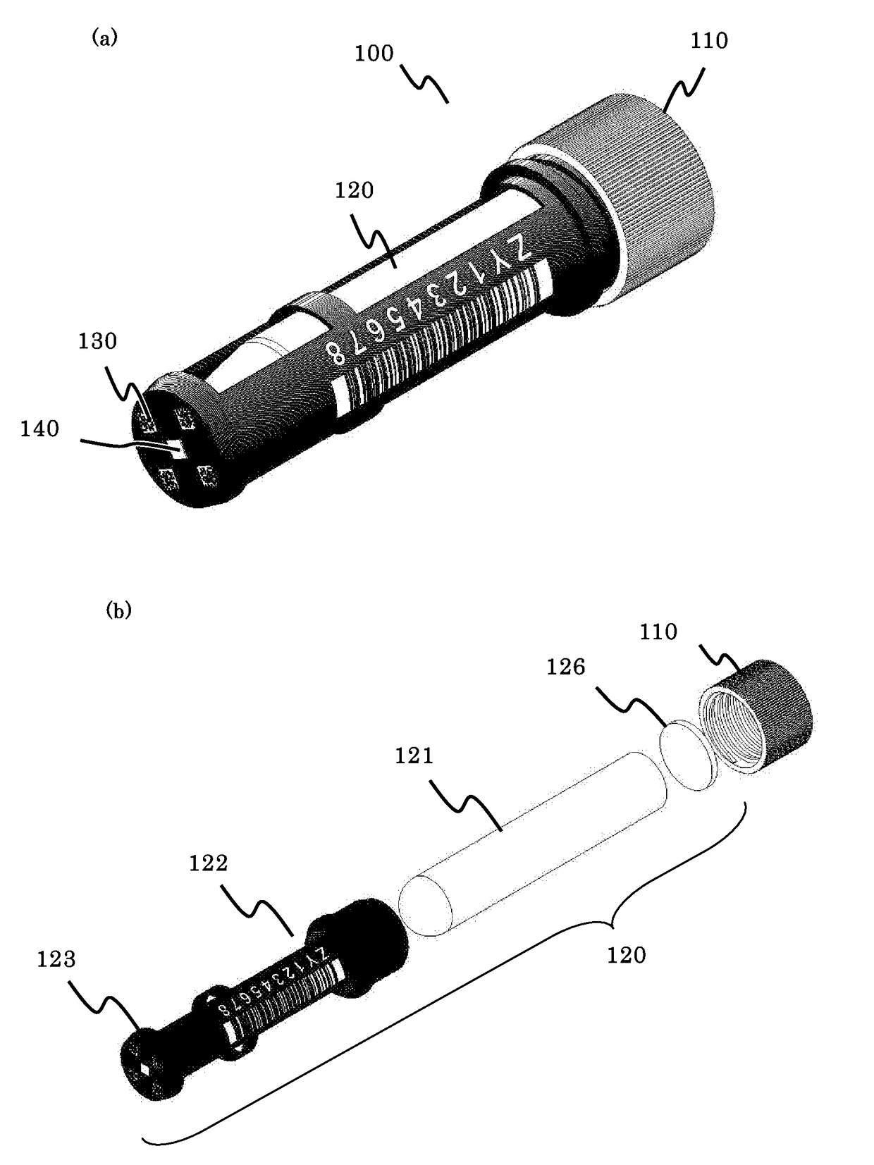
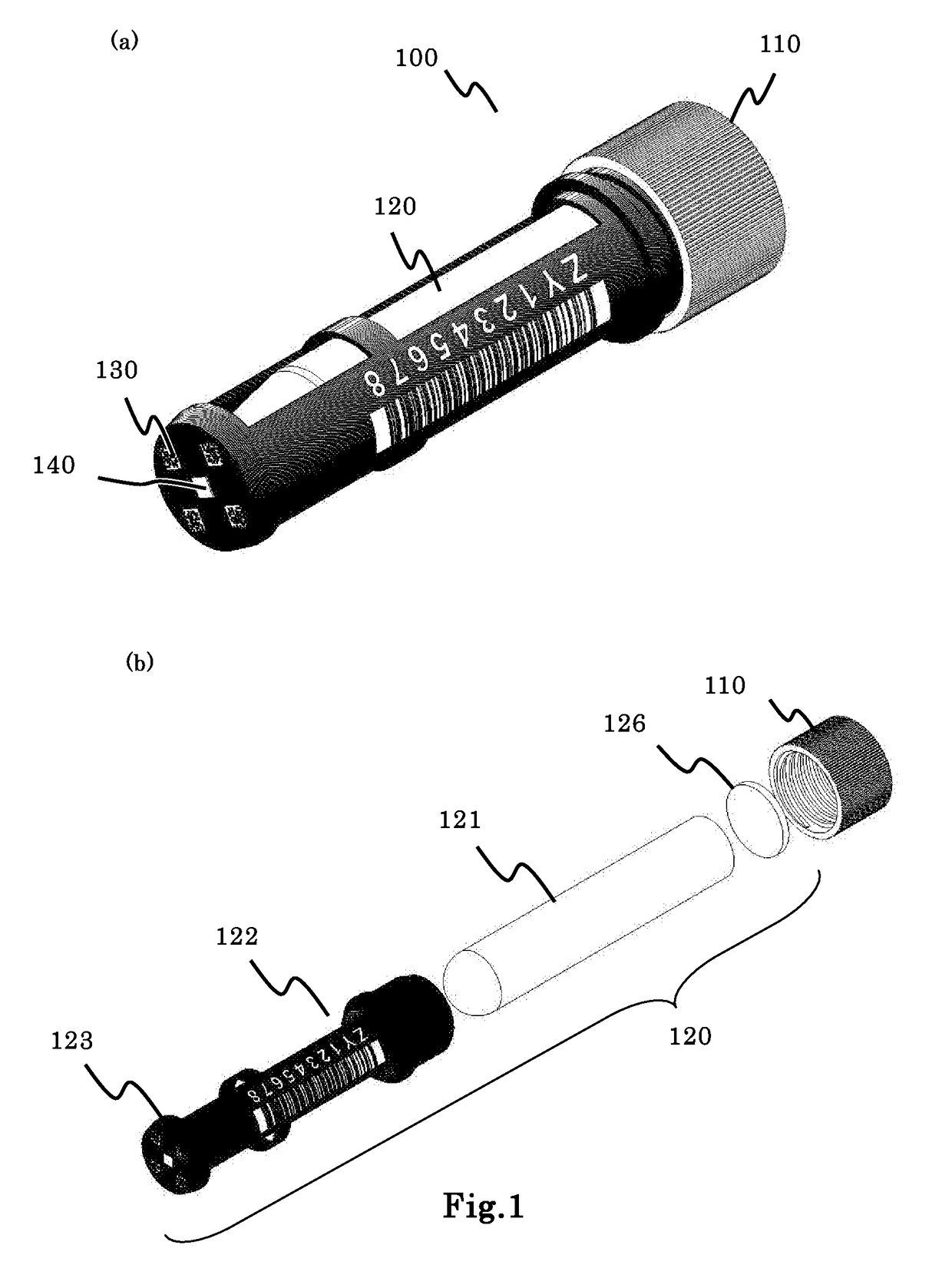
[0077]The sample storage tube 100 in embodiment 1 according to the present invention is described.

[0078]Embodiment 1 shows the structure of the sample storage tube 100 of the first pattern. The sample storage tube 100 of the first pattern has the configuration in which the bottom shape of the micro tube is circular and the printed information code is two-dimension code encoded by general specification. The wireless IC chip is embedded in the information non-writable area. In this example the sample storage tube is formed by the two-color injection molding. However, the manufacturing method is not limited to the two-color injection molding.

[0079]FIG. 1 is a schematic view of the structure of the sample storage tube 100. This example employs an outer screw type, but an inner screw type can be employed instead. FIG. 1 mainly shows the bottom of the sample storage tube 100 because the bottom structure is important.

[0080]FIG. 1 (a) is a perspective view emphasizing the bottom structure.

[...

embodiment 2

[0124]The second pattern of the sample storage tube in embodiment 2 according to the present invention is described. The sample storage tube in embodiment 2 employs the wireless IC chip embedded in the information non-writable area.

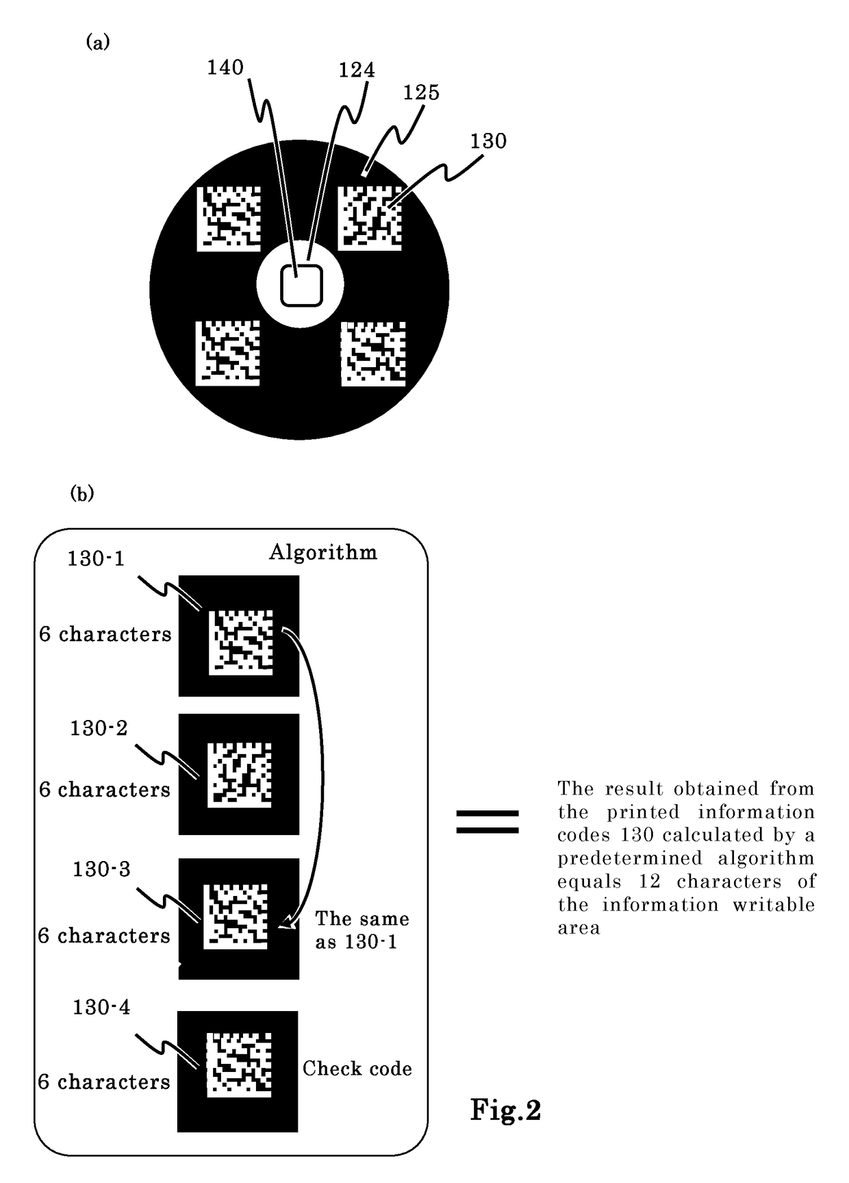
[0125]The second pattern is that the bottom shape of the micro tube is a polygon (for example, square) and the printed information code is two-dimension code encoded by general specification.

[0126]In this second pattern, plural general two-dimension codes are printed in the information writable area arranged in each corner of the bottom.

[0127]FIG. 4 is a schematic view of the structure of the sample storage tube 100a of the second pattern.

[0128]This example employs an outer screw type, but an inner screw type can be employed instead. FIG. 4 mainly shows the bottom of the sample storage tube 100a because the bottom structure is important.

[0129]FIG. 4 (a) is a perspective view emphasizing the bottom structure.

[0130]FIG. 4 (b) is an enlarged schematic view s...

embodiment 3

[0146]Embodiment 3 describes the configuration sample storage tube of the present invention in which a wireless IC chip is not installed in the information non-writable area, and the inside of the inner cylindrical tube is observed through the center portion.

[0147]There are various combinations of the bottom shape, the shape of the information writable area and the types of the printed information code for the tube body that does not have any wireless IC chip. For example, the configuration shown in Embodiment 1 from which the wireless IC chip is eliminated and the configuration shown in Embodiment 2 from which the wireless IC chip is eliminated can be counted as the example of this Embodiment 3. As an example, the configuration with the bottom shape that is circular and the printed information code is two-dimensional dot code encoded by general specification can be used.

[0148]FIG. 7 is a schematic view of the structure of the sample storage tube 100c of the Embodiment 3.

[0149]FIG. ...


PUM

PropertyMeasurementUnit
sizeaaaaaaaaaa
sizeaaaaaaaaaa
sizeaaaaaaaaaa

Abstract

[Problem to be solved] To provide a sample storage tube wherein the two-dimensional code and the wireless IC chip are equipped, and there is low interference between the two elements, which can ensure data reading and writing accuracy and reliability.[Solution] A sample storage tube 100 comprise a tube body 120 for storing a sample; a lid 110 for capping the upper opening of the tube body; an information writable area 124 for writing information installed to a bottom surface of the tube body; wherein the information writable area 124 is arrayed in a peripheral portion of the bottom 123; and an information non-writable area 125 in which any information cannot be written is secured in a center part of the bottom 123. Plural of printed information codes 130 are printed on the information writable area 124. The sizes of the shapes of the printed information code are small, and the amount of the information carried by each printed information code is smaller than the amount of the information to be applied to the information writable area of the sample storage tube. The result obtained from the printed information codes 130 calculated by a predetermined algorithm equals the information writable area of the sample storage tube.

Description

TECHNICAL FIELD[0001]This invention relates to a sample storage tube for storing and holding various samples. For example, the sample storage tube is used in holding and storing medicine samples being developed. Also, it is used for storing, refrigerating, freezing and preserving samples that hold gene information of DNA in the medical field. As such a sample storage tube becomes small, it is called a micro tube.[0002]This invention relates to an automation system for capping a lid to a sample storage tube, decapping the lid from the sample storage tube, and carrying the sample storage tube by grabbing and moving it from the predetermined place to the other predetermined place by its robot arm.BACKGROUND ART[0003]In the research and development of medicine and chemicals, sample storage tubes are used extensively in storing a large number of samples. For example, scientists prepare a large number of samples for a comparative experiment with slightly changing conditions such as blendi...

Claims


Application Information

Patent Timeline
Patent Type & Authority Applications(United States)
IPC IPC(8): B01L3/00G01N35/04G01N35/00
CPCB01L3/50825G01N35/04G01N35/0099G01N35/00732B01L3/5453B01L2300/041B01L2300/021B01L2300/024G01N2035/00772G01N35/02B01L2300/022B01L2300/0654B01L2300/0854G01N1/00
Inventor UEYAMA, YUKIO
Owner KOBE BIO ROBOTIX
Why Eureka
Try Eureka