Substrate processing apparatus and method of processing substrate

a substrate and processing apparatus technology, applied in the direction of coating, coating, chemical vapor deposition coating, etc., can solve the problem of electric discharge in the region below the stage, and achieve the effect of avoiding the formation of a spherical layer

Pending Publication Date: 2018-06-07
ASM IP HLDG BV
View PDF4 Cites 237 Cited by
  • Summary
  • Abstract
  • Description
  • Claims
  • Application Information

AI Technical Summary

Benefits of technology

[0009]Other and further objects, features and advantages of t...

Problems solved by technology

In a case where the profile of a formed film is controlled by adjusting the rate of flow of the ...

Method used


Image

  • Substrate processing apparatus and method of processing substrate
  • Substrate processing apparatus and method of processing substrate
  • Substrate processing apparatus and method of processing substrate

Examples


embodiment

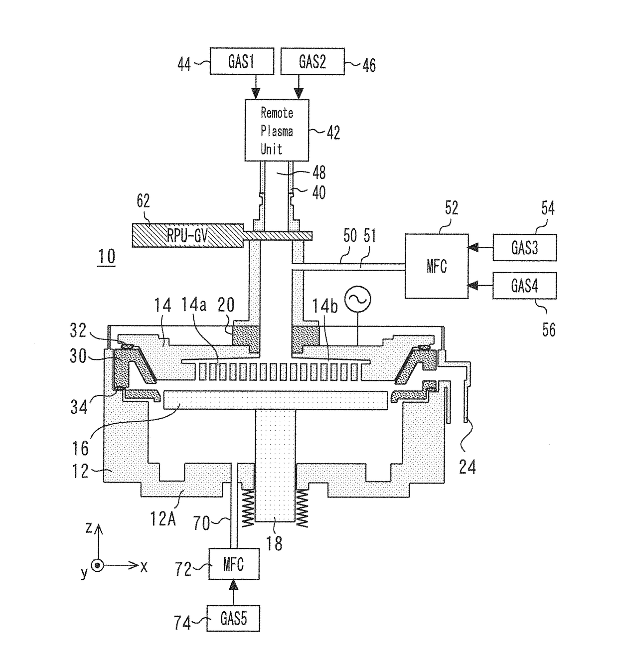
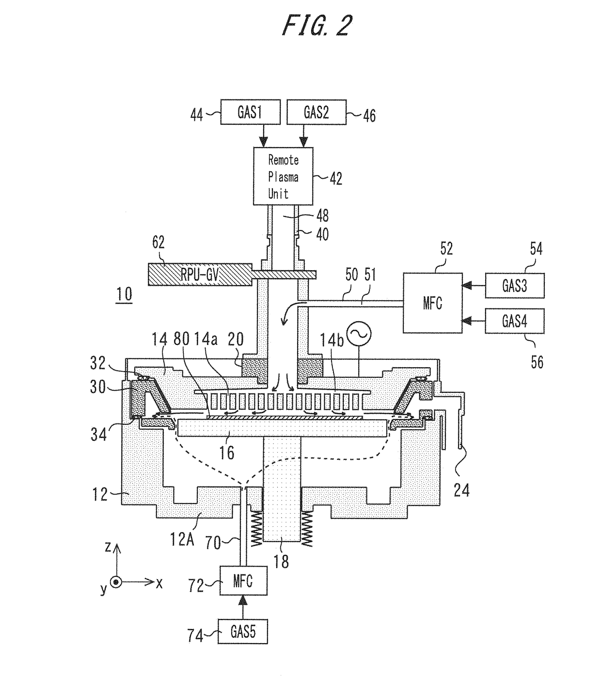
[0017]FIG. 1 is a sectional view of a substrate processing apparatus according to an embodiment of the present invention. The substrate processing apparatus has a chamber (reactor chamber) 12. A stage 16 is provided in the chamber 12. The stage 16 is, for example, a susceptor incorporating a heater. The stage 16 is supported on a slide shaft 18 and is grounded. A shower head 14 is provided above and in opposition to the stage 16. A plurality of slits 14a are formed in the shower head 14. In the shower head 14, a diffusion space 14b which communicates with the plurality of slits 14a is provided. The stage 16 and the shower head 14 form a plane-parallel structure.

[0018]A gas exhaust part 24 is provided on a side surface of the chamber 12. The gas exhaust part 24 is provided for the purpose of discharging gases including a material gas used for film forming. A vacuum pump is therefore connected to the gas exhaust part 24.

[0019]The stage 16 is surrounded by an exhaust duct 30 having suc...


PUM

PropertyMeasurementUnit
Thicknessaaaaaaaaaa
Flow rateaaaaaaaaaa
Shapeaaaaaaaaaa

Abstract

A substrate processing apparatus includes a stage provided in a chamber, a shower head in which a plurality of slits are formed and which is opposed to the stage, a first gas supply part which supplies a first gas to a space between the stage and the shower head via the plurality of slits, and a second gas supply part which supplies a second gas which is not a noble gas to a region below the stage, wherein the second gas is the same gas as one of a plurality of kinds of gases constituting the first gas in a case where the first gas is a mixture gas constituted of the plurality of kinds of gases, and the second gas is the same gas as the first gas in a case where the first gas is a single kind of gas.

Description

BACKGROUND OF THE INVENTIONField of the Invention[0001]The present invention relates to a substrate processing apparatus used to process a substrate such as a semiconductor wafer and to a method of processing a substrate by using the substrate processing apparatus.Background Art[0002]U.S. Pat. No. 9,123,510B2 discloses a substrate processing apparatus in which a process gas is supplied to a processing space via openings in a gas diffusion plate.[0003]In some cases, a substrate supported on a stage is processed by supplying a cleaning gas or a film forming gas from above the stage. For example, in such cases, an inert gas such as He or Ar is caused to flow through a region below the stage so that the gas supplied from above the stage does not flow below the stage in a roundabout way. The gas caused to flow through the region below the stage is referred to as “sealing gas” in some cases. When the amount of the gas supplied from above the stage is increased, it is necessary to also inc...

Claims


Application Information

Patent Timeline
IPC IPC(8): C23C16/455C23C16/44
CPCC23C16/4412C23C16/45565H01L21/3065H01L21/67069C23C16/452C23C16/505H01L21/67017H05H1/46H01J37/32174
Inventor ARAI, HIROKIMORI, YUKIHIRONONAKA, YUYA
Owner ASM IP HLDG BV
Why Eureka
Try Eureka