Ignition system for internal combustion engine

a technology for internal combustion engines and ignition systems, which is applied in the direction of electric ignition installation, machines/engines, mechanical equipment, etc., can solve the problems of increasing the cost of the ignition system of the internal combustion engin

Inactive Publication Date: 2018-06-07
BRIGGS & STRATTON LLC
View PDF3 Cites 3 Cited by
  • Summary
  • Abstract
  • Description
  • Claims
  • Application Information

AI Technical Summary

Benefits of technology

[0017]In another contemplated embodiment, the ignition system is designed to interface with an engine control unit (ECU) that is programmed to control the application of current through two separate primary windings each assigned to one of two cylinders of an internal combustion engine. The ignition system converts the low value triggering output signals from the EC

Problems solved by technology

This use of multiple windings increases the cost of t

Method used


Image

  • Ignition system for internal combustion engine
  • Ignition system for internal combustion engine
  • Ignition system for internal combustion engine

Examples


Embodiment Construction

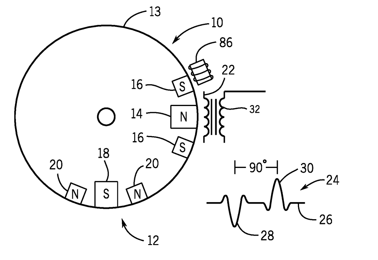
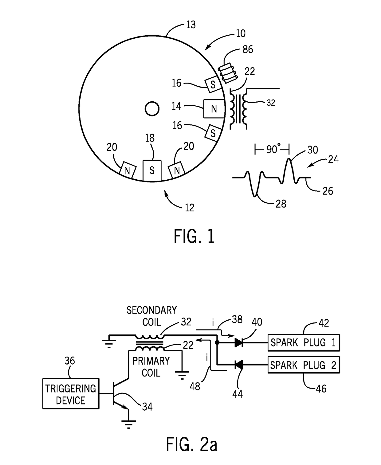
[0039]FIG. 1 illustrates a flywheel 10 that forms part of an ignition system of the present disclosure. The flywheel 10 is a circular member having a series of permanent magnet clusters positioned at regular intervals along the outer circumference 13 of the flywheel. In the embodiment shown in FIG. 1, magnetic clusters 12 are positioned 90° from each other along the outer circumference of the flywheel 10. Although the magnetic clusters 12 shown in FIG. 1 are spaced at a 90° interval, it is contemplated that the magnetic clusters 12 could be spaced at other intervals, such as 180° or 60°.

[0040]As illustrated in FIG. 1, the magnetic clusters 12 positioned 90° apart have different orientations. In the embodiment shown in FIG. 1, the magnetic cluster 12 positioned at the 3 o'clock position has a large north magnetic pole 14 positioned between two smaller south magnetic poles 16. The magnetic cluster 12 positioned at the 6 o'clock position includes a large south magnetic pole 18 position...


PUM


Abstract

An ignition system for an internal combustion engine that utilizes a single primary coil and a single secondary coil to drive a pair of spark plugs. Current flowing in both a first direction and a second direction passes through the primary coil. The current flowing through the primary coil induces corresponding current in the secondary coil, which flows from the secondary coil to one of two spark plugs. Each spark plug is coupled to the secondary coil such that each of the two spark plugs receives current flowing only in a single direction. The current flowing through the ignition system can be from either a power source or created by the rotation of a flywheel having a series of magnet clusters.

Description

CROSS REFERENCE TO RELATED APPLICATION[0001]This application is a continuation-in-part application of prior U.S. patent application Ser. No. 15 / 406,279, filed on Jan. 13, 2017, which is a continuation-in-part application of prior U.S. patent application Ser. No. 15 / 286,799, filed on Oct. 6, 2016, which is a divisional application of prior U.S. patent application Ser. No. 13 / 283,697, filed on Oct. 28, 2011, now issued as U.S. Pat. No. 9,488,150, entitled IGNITION SYSTEM FOR INTERNAL COMBUSTION ENGINE.BACKGROUND[0002]The present disclosure relates to an ignition system for an internal combustion engine. More specifically, the present disclosure relates to an ignition system that utilizes a single primary coil and a single secondary coil to provide current to more than one spark plug of an internal combustion engine.[0003]Inductive ignition systems for internal combustion engines are known and typically utilize a permanent magnet connected to a flywheel that rotates along with a cranks...

Claims


Application Information

Patent Timeline
IPC IPC(8): F02P3/04F02P15/08F02P1/08
CPCF02P15/08F02P1/083F02P3/0407F02P5/1502Y02T10/40
Inventor KOENEN, ROBERT J.PASKOV, ANDREWHANSEN, JASON A.
Owner BRIGGS & STRATTON LLC
Why Eureka
Try Eureka