Panel and associated attachment devices

a technology of attachment devices and panels, which is applied in the direction of photovoltaics, heat collector mounting/support, moving/orienting solar heat collectors, etc., can solve the problems of degrading the reliability of the holding of modules, imposing extra costs of more than 10%, and affecting the installation of metal frames

Active Publication Date: 2018-06-07
A RAYMOND & CO
View PDF5 Cites 2 Cited by
  • Summary
  • Abstract
  • Description
  • Claims
  • Application Information

AI Technical Summary

Benefits of technology

[0017]a metal clip cooperating by fitting together with the lug and configured so as to allow the pivoting of the lug when the panel flexes. The panel according to this disclosure is provided with reliable metal attachment devices, not liable to degrade over time. The system for attachment by clip procures a high level of mechanical strength and is simple to implement. The connection between the lug and the clip allowing a pivoting movement of one with respect to the other, the resistance of the module to the forces resulting from a high weight load is increased: this is because, when the panel flexes, the lug bonded to it is able to pivot vis-à-vis the clip, which limits a concentration of stresses appearing typically at the edges of rigid attachments.
[0021]the clip comprises two facing walls defining a fitting-together space making it possible to introduce the lug into the clip on a fitting-together axis;
[0022]the lug comprises two facing walls defining a fitting-together space making it possible to introduce the clip along a fitting-together axis;
[0032]The attachment device according to this disclosure allows a pivoting movement between the lug and the clip, as well as a limited translation movement along the coupling axis. These degrees of freedom of movement make it possible to accompany the panel when it flexes and limit the stress concentration points. The attachment device according to this disclosure blocks the translation movement along the axis perpendicular the coupling axis, in the plane of the main faces of the panel: this prevents any damage to the edges of the panels by contact and / or rubbing between two adjacent panels.

Problems solved by technology

In particular, an extra cost of more than 10% is imposed by the presence of the metal frame.
The main drawback of this type of attachment nevertheless remains the degradation that the elastomer parts of the attachment elements suffer, in particular because of the severe climatic conditions to which the modules are exposed and because of the mechanical stresses suffered during the flexing of the modules.
The reliability of holding of the modules is degraded thereby: when there is a high force, resulting from a high weight load, the edges of the modules risk being extracted from the attachment, thus causing damage to the PV module.
The major drawback of this type of attachment lies in the shadow caused at the rear face of the module, which is detrimental to the performance of a dual-face module.

Method used


Image

  • Panel and associated attachment devices
  • Panel and associated attachment devices
  • Panel and associated attachment devices

Examples


first embodiment

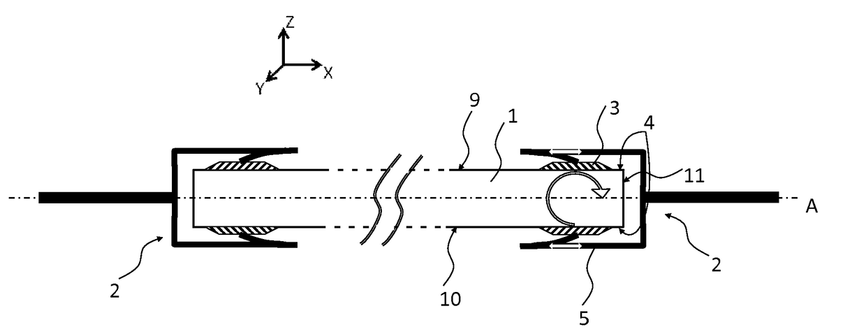
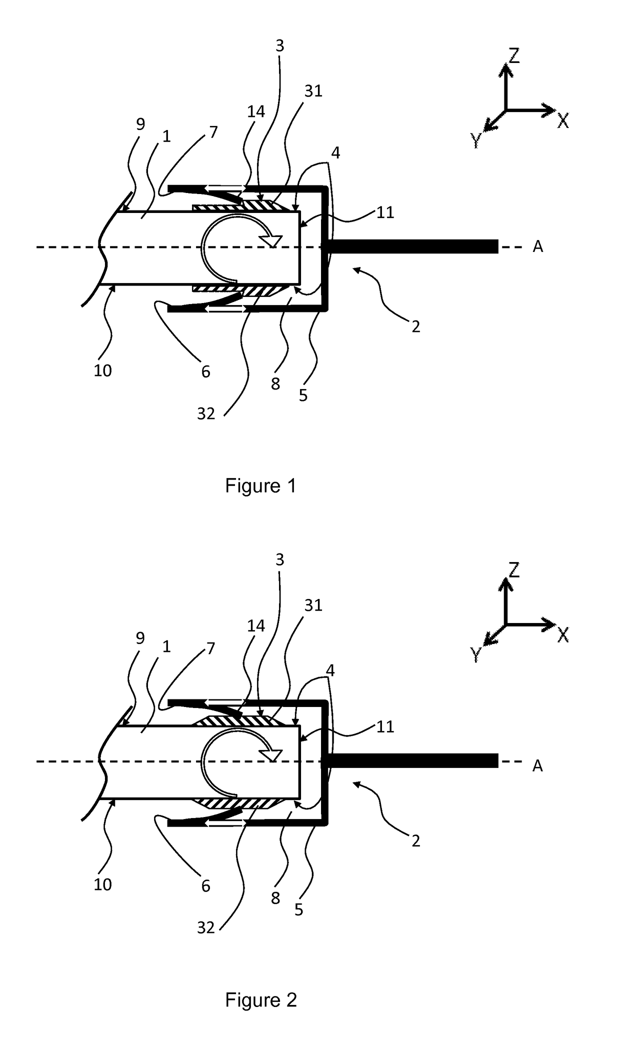
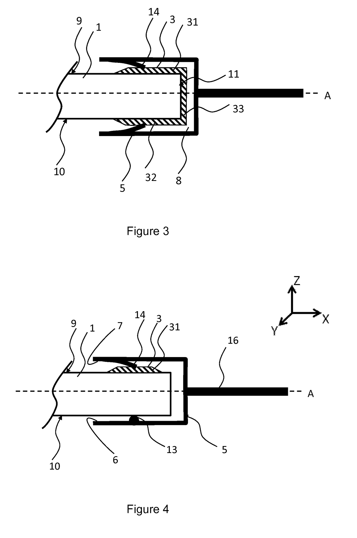
[0065] presented in FIG. 1, the lug 3 consists of two parts 31, 32, respectively bonded to a peripheral part of the two main faces 9, 10 of the panel 1. The lug 3 consists of a metal material and is bonded to the panel 1 by means of an adhesive substance affording strong adhesion between metal / glass or metal / polymer surfaces, chosen from silicone, epoxy or polyurethane glues.

[0066]By way of example, the dimensions of each of the parts 31, 32 of the lug 3 consist of:

[0067]a length (along the axis Y shown schematically in FIG. 1) lying between 50 and 100 mm, advantageously equal to 80 mm;

[0068]a width (along the axis X shown schematically in FIG. 1) by between 10 and 20 mm, advantageously equal to 15 mm;

[0069]a thickness (along the axis Z shown schematically in FIG. 1) lying between 2 and 4 mm, advantageously equal to 3 mm.

[0070]Each part of the lug 3 comprises a shoulder of around 0.1 to 0.5 mm, shown schematically in FIG. 1, which will make it possible to lock the clip 5 after it is...

second embodiment

[0079]According to this second embodiment of this disclosure, the clip 5 encloses the two parts 31, 32 of the lug 3 and a peripheral part of the panel 1. The panel 1 nevertheless has degrees of freedom of movement: in pivoting firstly, as shown schematically by the arrow in an arc of a circle in FIG. 2. This movement makes it possible to accompany the flexing of the panel 1 and avoids creating a stress concentration point by flat contact of the panel 1 on the walls 6, 7 of the clip 5. Pivoting is possible because of a sufficient free space, provided in the coupling space 8, and the flexible character of the tongues 14. The spacing between each wall 6, 7 of the clip 5 and the part 31, 32 of the lug 3 facing is around 2 to 3 mm.

[0080]Moreover, the panel 1 has a degree of freedom of movement in translation, along the coupling axis A, as illustrated by the two white arrows in FIG. 2. The amplitude of this translation movement is nevertheless limited. This is because it is blocked in the...

third embodiment

[0086]FIG. 5 presents a third embodiment according to this disclosure. The lug 3, bonded on the peripheral surface of the panel 1, comprises three parts 31, 32, 33 forming a U-shaped bracket. It further comprises an offset part 12 having two opposite free faces U, V to which the clip 5 is attached. The attachment is done by means of tongues clamped on these two faces or locked by shoulders present on these two faces. In this case, the clip 5 grips only the offset part 12 of the lug 3, and not the peripheral part of the panel 1. The offset part 12 of the lug 3 has degrees of freedom of movement in pivoting and translation (limited) as shown by the white arrows in FIG. 5. This makes it possible to accompany the movement of the panel 1 during flexing under weight load.


PUM


Abstract

The present disclosure concerns a panel capable of bending under the effect of a load and having a peripheral surface provided with a plurality of pivoting attachment devices; each attachment device comprises: a metal gripping member adhered to the peripheral surface of the panel; and a metal clip cooperating by interlocking with the gripping member and configured to allow the gripping member to pivot when the panel bends.

Description

CROSS-REFERENCE TO RELATED APPLICATION[0001]This application is a national phase entry under 35 U.S.C. § 371 of International Patent Application PCT / FR2016 / 051302, filed Jun. 1, 2016, designating the United States of America and published as International Patent Publication WO 2016 / 193614 A1 on Dec. 8, 2016, which claims the benefit under Article 8 of the Patent Cooperation Treaty to French Patent Application Serial No. 1554926, filed Jun. 1, 2015, for “Panel and Associated Attachment Devices,” the contents of each of which are incorporated herein in their entirety by this reference.TECHNICAL FIELD[0002]This disclosure relates to the field of large panels and associated attachment devices. It relates in particular to devices for attaching solar modules, in particular frameless dual-face solar modules.[0003]Currently, more than 90% of photovoltaic (PV) modules comprise a metal frame made from aluminium for stiffening the modules manufactured from an assembly of a glass plate on the f...

Claims


Application Information

Patent Timeline
Patent Type & Authority Applications(United States)
IPC IPC(8): F24S30/00
CPCF24S2080/09F24S40/80F24S2025/601F24S25/632F24J2/5256F24J2/4636F24J2/5254F24J2002/4676F24J2002/4656F24S25/634F24S25/33F24S2025/014F24S2025/016H01L31/048H01L31/0488H02S20/22F24S2025/018F24S2025/6004Y02B10/10Y02E10/47Y02E10/50
Inventor CHEVRIER, JEAN-BAPTISTELEGALL, ANTOINEPETRI, RICHARDTURLOT, EMMANUEL
Owner A RAYMOND & CO
Why Eureka
Try Eureka