Tunable mass damper characterization test stand

a technology of damper and characterization, which is applied in the direction of vibration testing, structural/machine measurement, measurement devices, etc., can solve the problems of increasing the chance of scale effects in the wind tunnel data, introducing experimental artifacts, and affecting any efforts

Active Publication Date: 2018-06-07
THE BOEING CO
View PDF3 Cites 6 Cited by
  • Summary
  • Abstract
  • Description
  • Claims
  • Application Information

AI Technical Summary

Benefits of technology

[0012]In some embodiments, a system for testing a tunable mass damper may include a test stand configured to provide a repeatable impulse to the tunable mass damper. The test stand may include (a) a support base, (b) a test plate coupled to the support base, the test plate configured to move relative to the support base and to fixedly carry a tunable mass damper, (c) a biasing member urging the test plate away from the support base, (d) a loading member configured to move the test plate relative to the support base against the urging of the biasing member, and (e) a release mechanism configured to release the test plate from the loading member when the test ...

Problems solved by technology

An inherent complication of wind tunnel testing is the introduction of experimental artifacts that would not be present in a real-world setting.
These forces would obviously not be present on a real-world aircraft, and can interfere with any efforts to measure the forces on the model that arise from the aerodynamic performance of the model itself.
This solution has the disadvantage of increasing the chance of scale effects in the wind tunnel data.
However, increasing the balance capacity would tend to decr...

Method used


Image

  • Tunable mass damper characterization test stand
  • Tunable mass damper characterization test stand
  • Tunable mass damper characterization test stand

Examples


example 1

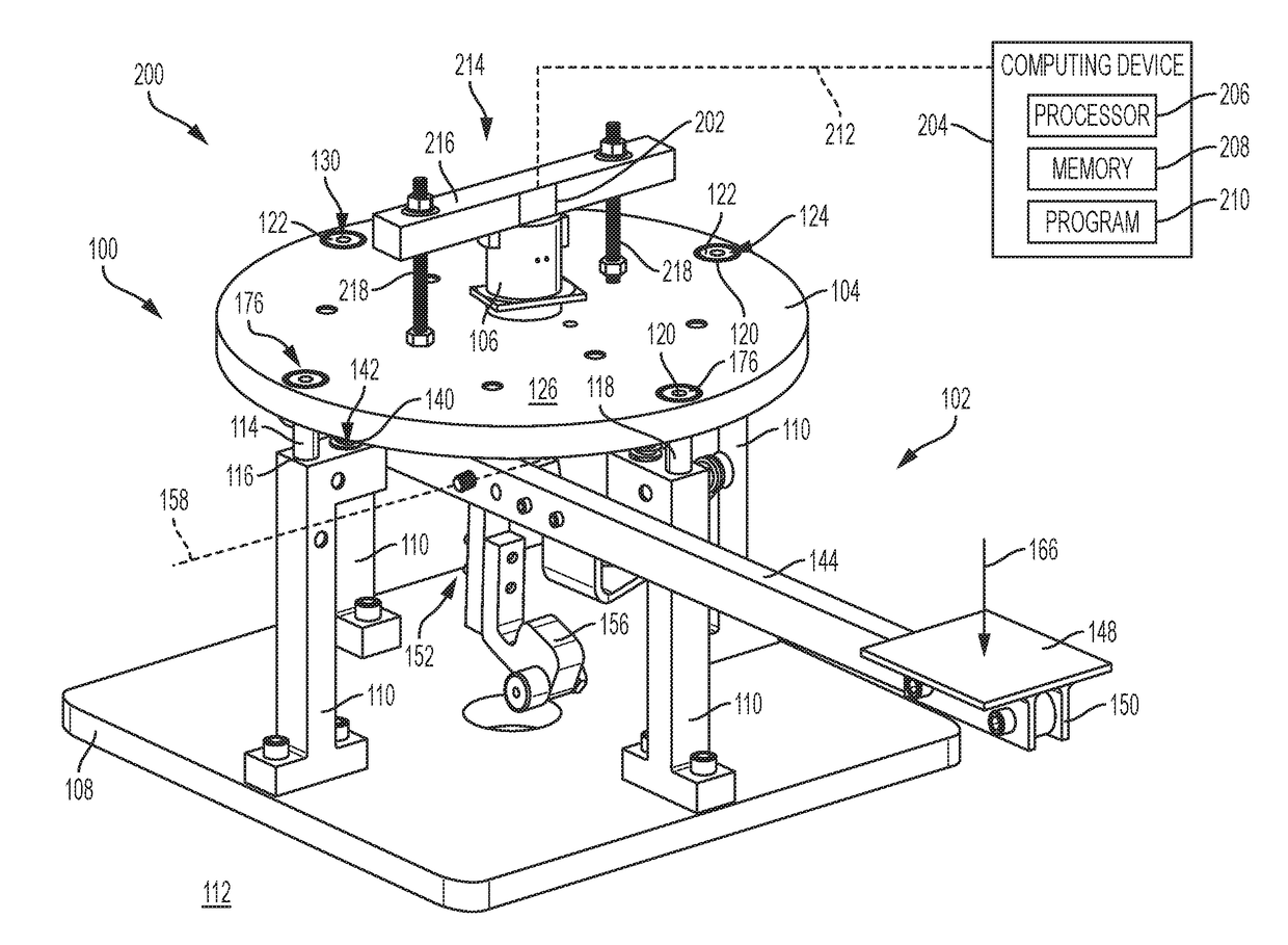
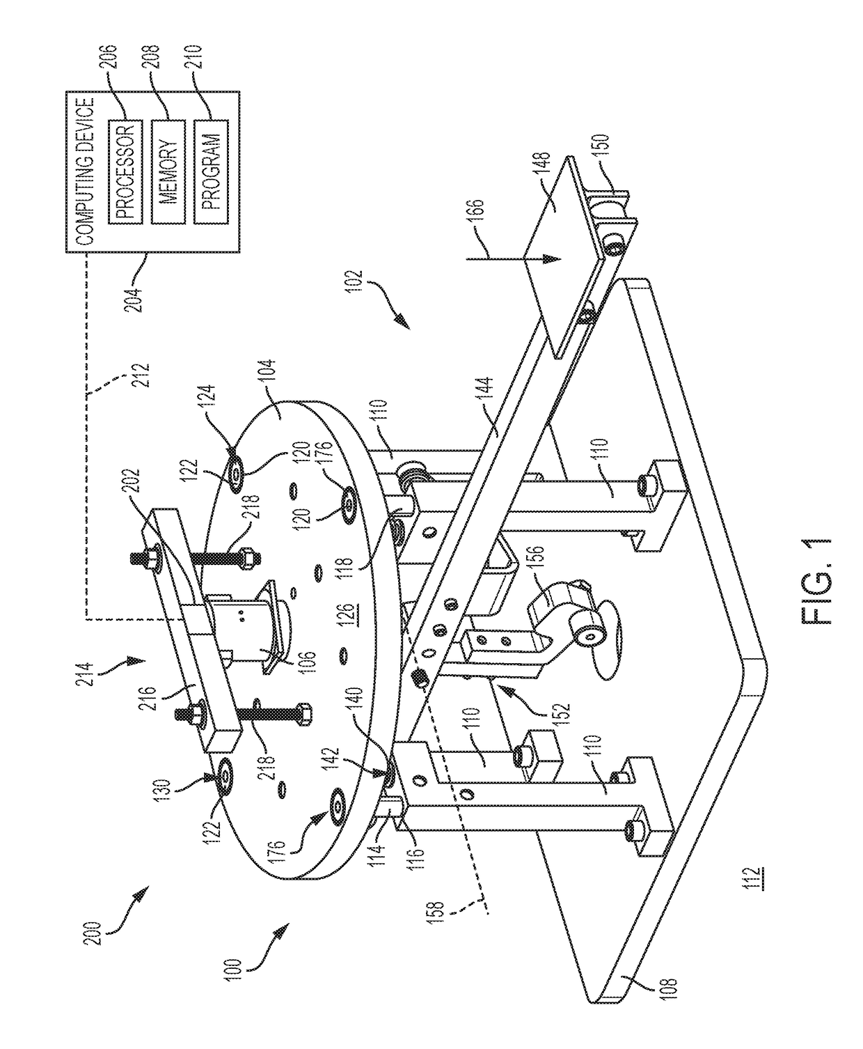
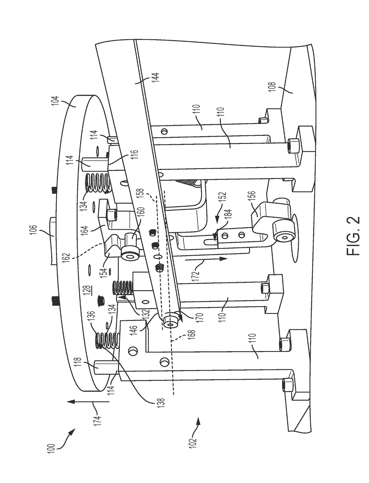
[0033]This example describes an illustrative test stand for characterization of a tunable mass damper; see FIGS. 1-5.

[0034]FIG. 1 is an upper trimetric view of an illustrative embodiment of a test stand for characterization of a tunable mass damper, the test stand generally indicated at 100. FIG. 2 is a lower perspective view of test stand 100. FIGS. 1 and 2 are herein described together. Test stand 100 includes a support base 102 and a test plate 104 coupled to the support base. The test plate is configured to move relative to the support base and to fixedly carry a tunable mass damper (TMD) 106.

[0035]Support base 102 may include a base plate 108 and a plurality of support legs 110 coupled to the base plate. Base plate 108 may be configured to be supported on a work surface 112 such as a table, a desk, or a floor. In some examples, base plate 108 may be secured to the work surface by a clamp, bolts, or some other appropriate fastener. In some examples, base plate 108 may rest on wo...

example 2

[0073]This example describes an illustrative method of characterizing the oscillation properties of a tunable mass damper, which may be used in conjunction with any of the apparatuses or systems described herein; see FIG. 6.

[0074]FIG. 6 depicts multiple steps of a method, generally indicated at 300 of characterizing the oscillation properties of a tunable mass damper. Method 300 may be used in conjunction with any of the test stands depicted in and described in reference to FIGS. 1-5 and 8. Although various steps of method 300 are described below and depicted in FIG. 6, the steps need not necessarily all be performed, in some cases may be performed in a different order than the order shown, in some cases may be performed more than once, and in some cases may be performed simultaneously.

[0075]Method 300 may include a step 302 of mounting a tunable mass damper (TMD) to a test plate, the test plate being biased away from a support base by a spring. In some examples, mounting a TMD to a...

example 3

[0090]This examples describes an illustrative computing device; see FIG. 7.

[0091]As shown in FIG. 7, this example describes a data processing system 400 in accordance with aspects of the present disclosure. In this example, data processing system 400 is an illustrative data processing system suitable for implementing aspects of a system for testing a tunable mass damper. More specifically, in some examples, devices that are embodiments of data processing systems (e.g., smartphones, tablets, personal computers, oscilloscopes) may receive data from a detector, the data relating to the oscillation properties or characteristics of a tunable mass damper. The devices that are embodiments of data processing systems may identify or help to identify one or more oscillation characteristics of the tunable mass damper from the received data.

[0092]In this illustrative example, data processing system 400 includes communications framework 402. Communications framework 402 provides communications b...


PUM


Abstract

A test stand for characterization of a tunable mass damper may include (a) a support base including a stop member, (b) a test plate coupled to the support base, with the test plate configured to move relative to the support base and to fixedly carry a tunable mass damper, (c) a spring coupled to the support base and the test plate, (d) a lever configured to be releasably coupled to the test plate and to move the test plate relative to the support base against the urging of the spring, and (e) a latch mechanism configured to release the test plate from the lever when the test plate is at a predetermined position relative to the support base. The motion of the test plate, after the test plate has been released by the latch mechanism, may be halted by the stop member of the support base.

Description

CROSS-REFERENCES[0001]The following related applications are incorporated herein, in their entireties, for all purposes: U.S. patent application Ser. No. 14 / 477,701, filed Sep. 4, 2014; U.S. patent application Ser. No. 15 / 048,876 filed Feb. 19, 2016; and U.S. patent application Ser. No. 15 / 237,375, filed Aug. 15, 2016.FIELD[0002]This disclosure relates to wind tunnel testing of aircraft models. More specifically, the disclosed embodiments relate to systems and methods for characterizing oscillation properties of tunable mass dampers prior to installation of the dampers in aircraft models.INTRODUCTION[0003]Aerodynamic testing of models in wind tunnels is a common and important part of the aeronautics industry. Accurate testing is necessary for safety, and can potentially save millions of dollars by eliminating real-world test flights. An inherent complication of wind tunnel testing is the introduction of experimental artifacts that would not be present in a real-world setting. Such a...

Claims


Application Information

Patent Timeline
IPC IPC(8): G01M7/02
CPCG01M7/025G01M7/027G01M7/06
Inventor MCGRANAHAN, BRYAN D.
Owner THE BOEING CO
Why Eureka
Try Eureka