Systems and methods for generating a structured illumination image
- Summary
- Abstract
- Description
- Claims
- Application Information
AI Technical Summary
Benefits of technology
Problems solved by technology
Method used
Image

Examples
Embodiment Construction
.”
BRIEF DESCRIPTION OF THE DRAWINGS
[0019]Features, aspects, and embodiments are described in conjunction with the attached drawings, in which:
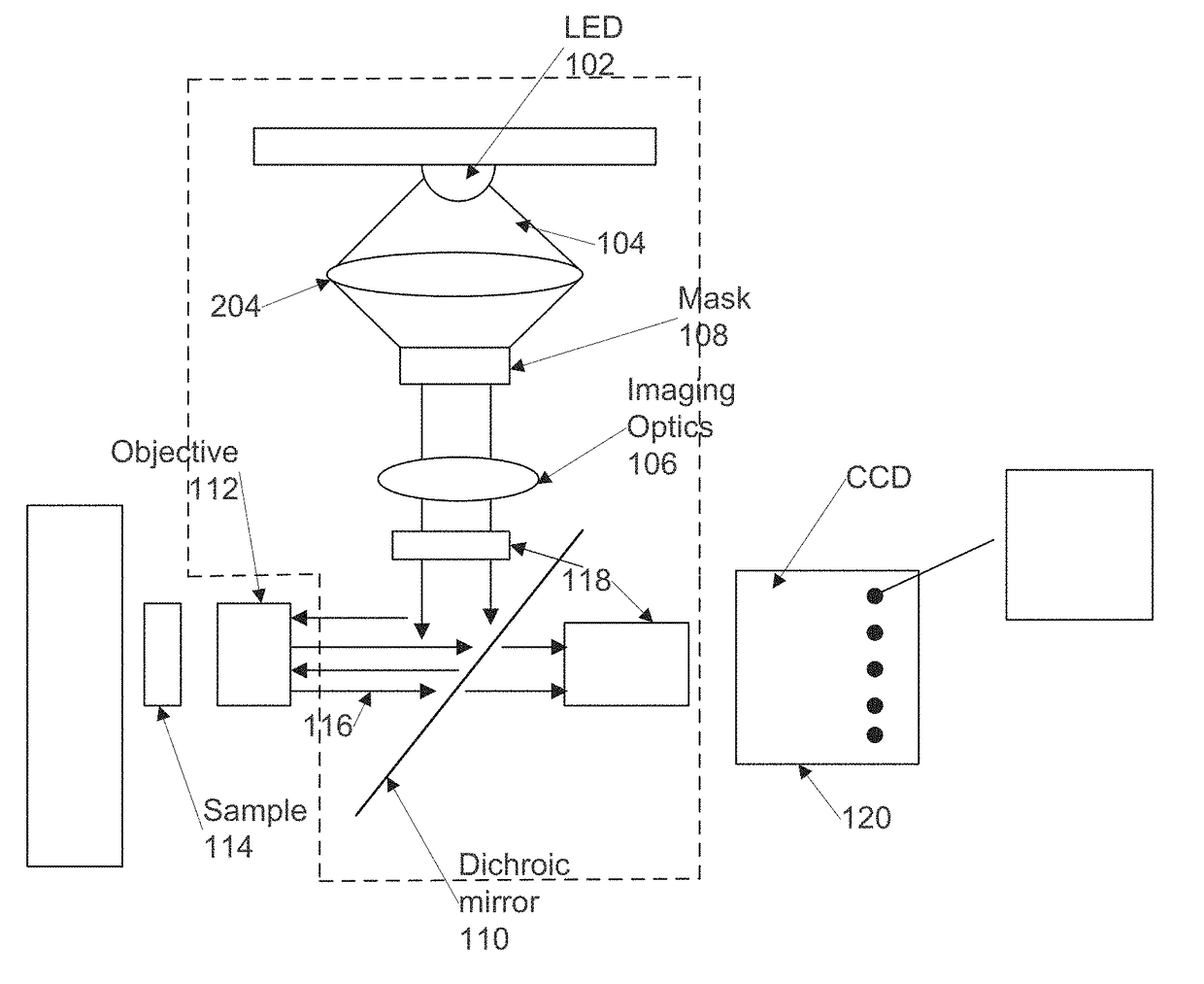
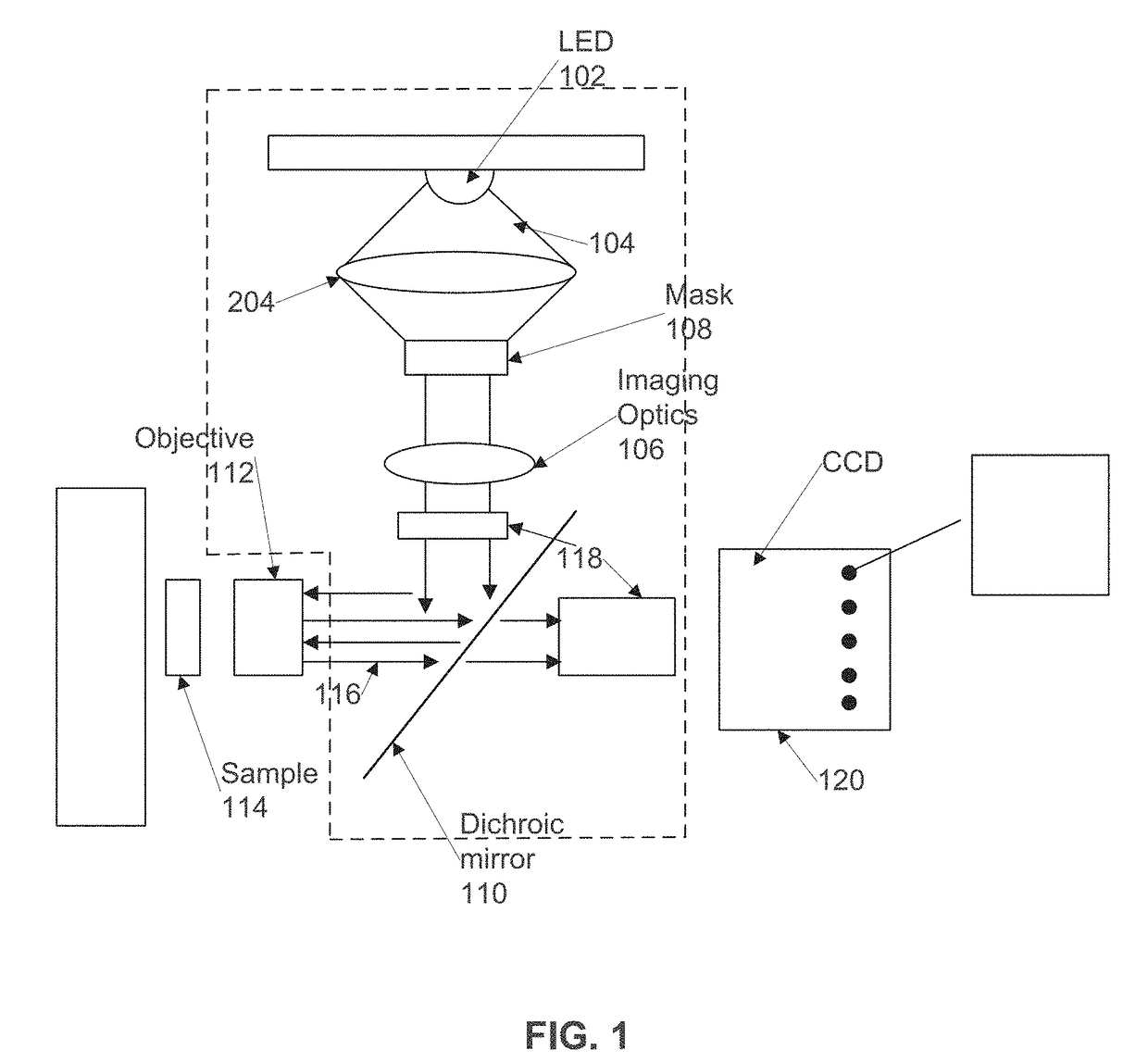
[0020]FIG. 1 is a diagram illustrating an example flouresence imaging system configured in accordance with one embodiment;
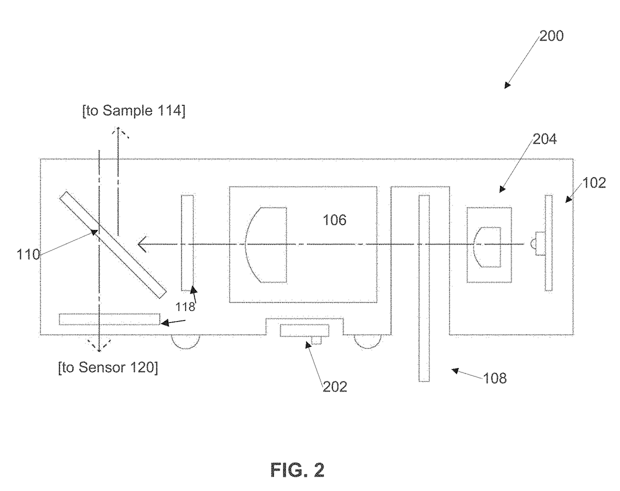
[0021]FIG. 2 is a diagram illustrating an example embodiment of a light cube implementation of at least some of the components of FIG. 1;
[0022]FIG. 3 is a flow chart illustrating an example process for eliminating periodic artifacts such as those produced by photobleaching in images captured using the system of FIG. 1 in accordance with one embodiment;
[0023]FIG. 4 is a diagram illustrating an example control system for controlling the operation of the illumination system of FIG. 1 in accordance with one embodiment;
[0024]FIG. 5 is a diagram illustrating an example pinhole mask that can be used in the system of FIG. 1, and in particular in the light cube implementation of FIG. 2 in accordance with one embodiment;
[0025]FIG. 6A...
PUM
 Abstract
Description
Claims
Application Information
 - Generate Ideas
- Intellectual Property
- Life Sciences
- Materials
- Tech Scout
- Unparalleled Data Quality
- Higher Quality Content
- 60% Fewer Hallucinations
Browse by: Latest US Patents, China's latest patents, Technical Efficacy Thesaurus, Application Domain, Technology Topic, Popular Technical Reports.
© 2025 PatSnap. All rights reserved.Legal|Privacy policy|Modern Slavery Act Transparency Statement|Sitemap|About US| Contact US: help@patsnap.com