Circuit structure using printed-circuit board

a printed circuit board and circuit structure technology, applied in the direction of printed circuit non-printed electric components association, programmable/customizable/modifiable circuit, high-current circuit adaptation, etc., can solve the problems of poor connection stability, increase in manufacturing costs involved in manufacturing and storage/maintenance of printed circuit boards having different specifications, etc., to achieve the effect of improving the efficiency of verification work, further compactness and effective

Active Publication Date: 2018-06-07
SUMITOMO WIRING SYST LTD
View PDF2 Cites 0 Cited by
  • Summary
  • Abstract
  • Description
  • Claims
  • Application Information

AI Technical Summary

Benefits of technology

[0018]According to this aspect, the bus bar support base is formed integrally with the power supply connector module mounted on the printed-circuit board. Since a plurality of circuit patterns are routed around the power supply connector module, it is possible to more effectively achieve the localized placement of the connection points of the circuit patterns below the bus bar support base, thus achieving further compactness.
[0019]According to the present invention, a plurality of types of circuit specifications can be provided by locally disposing the connection points of the plurality of circuit patterns below the bus bar support base of the circuit switching component mounted on the printed-circuit board, and changing the mounting mode of the connection bus bars to the bus bar support base. This makes it possible to improve the efficiency of the verification work, and reduce the risk of the circuit specification being misidentified as quickly as possible. Moreover, by localizing the connection points below the circuit switching component, the length of the connection bus bars can be minimized, so that the material costs and the like can be reduced. Also, the circuit switching can be performed with a compact structure, so that it is possible to advantageously solve the problem of interference between the members for circuit switching and other members. In addition, since the connection bus bars are mounted and held on the bus bar support base, it is possible to advantageously ensure connection stability between the circuits.

Problems solved by technology

With the recent increase in the number of types of printed-circuit boards to support different circuits according to the vehicle classification and the like, there has been concern over an increase in the manufacturing costs involved in the manufacturing and the storage / maintenance of such printed-circuit boards having different specifications.
Moreover, the provision of connection points at various locations on the printed-circuit board may pose such problems that the workability during soldering of the jumper wires and the lead wires to the circuit pattern may be impaired owing to the positional relationship with other mounted members, and that the length of the jumper wires may be increased to avoid interference with other members, resulting in poor connection stability.

Method used


Image

  • Circuit structure using printed-circuit board
  • Circuit structure using printed-circuit board
  • Circuit structure using printed-circuit board

Examples


Embodiment Construction

[0028]Hereinafter, an embodiment of the present invention will be described with reference to the drawings.

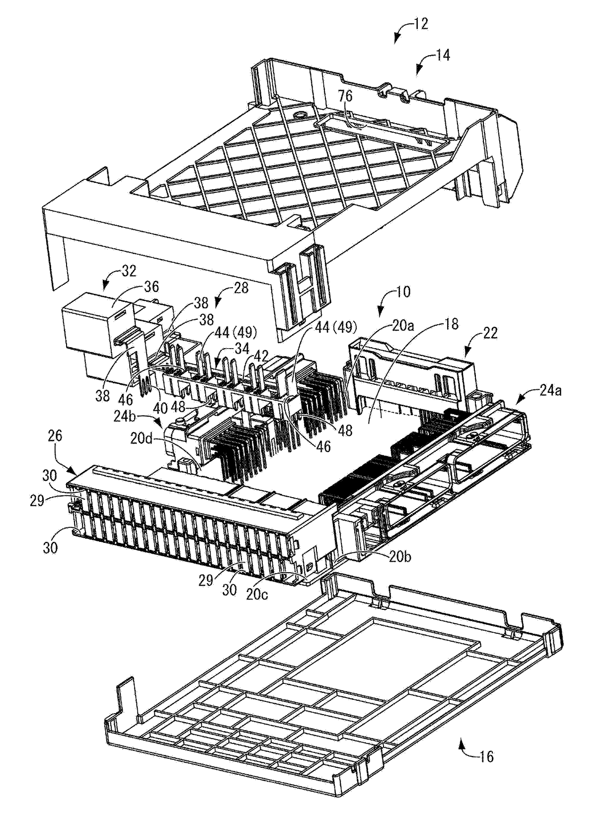
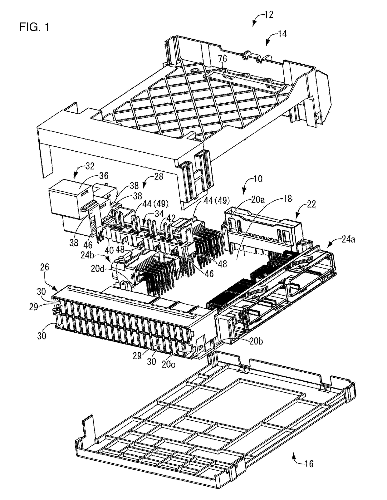
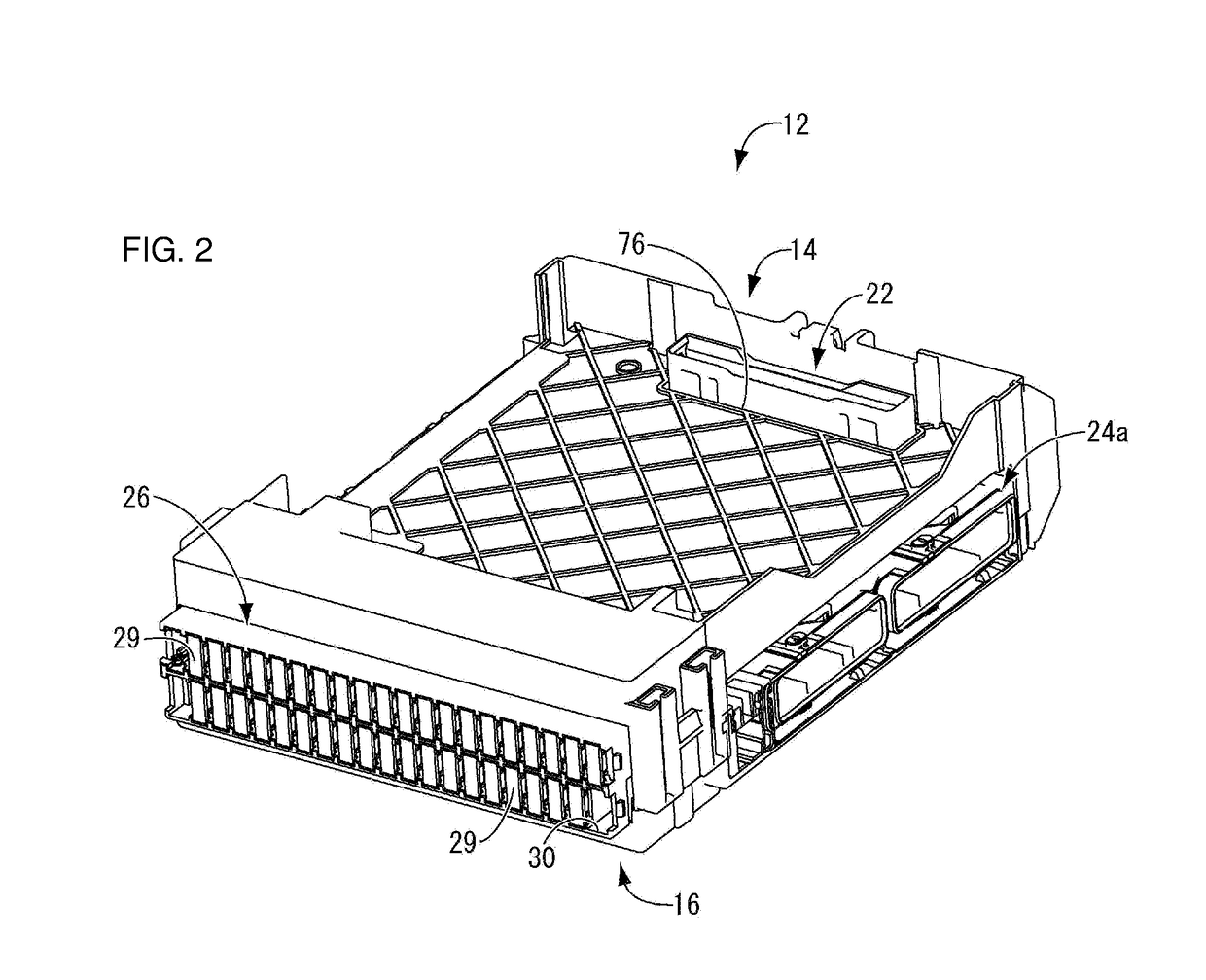
[0029]FIGS. 1 and 2 show an electrical junction box 12 in which a circuit structure 10 using a printed-circuit board according to an embodiment of the present invention is housed. As shown in FIG. 1, the electrical junction box 12 is structured such that the circuit structure 10 is housed between an upper case 14 and a lower case 16 each formed through injection molding or the like using a synthetic resin such as polypropylene (PP) or polyamide (PA). In the following description, “upward” refers to the upper case 14 side, “downward” refers to the lower case 16 side, “forward” refers to the downward direction in FIG. 3, and “rearward” refers to the upward direction in FIG. 3, unless otherwise specified.

[0030]As shown in FIGS. 1 and 3, the circuit structure 10 includes a printed-circuit board 18, and various members disposed at the central portion and outer peripheral portions 20...


PUM


Abstract

Provided is a circuit structure using a printed-circuit board with a novel structure that can provide a plurality of types of circuit specifications by switching connection of circuit patterns, allows circuit specifications to be easily identified, and achieves excellent connection workability and connection stability for circuit patterns. The circuit structure includes: a printed-circuit board 18 on which a plurality of circuit patterns are provided; and a circuit switching component, wherein the circuit switching component includes bus bar support bases on which any connection bus bars selected can be mounted and held, the plurality of types of connection bus bars are classified according to the number and the position of lead portions to be electrically connected to connection points, and a plurality of types of circuit specifications are provided by changing a mounting mode of the connection bus bars to the bus bar support bases.

Description

CROSS-REFERENCE TO RELATED APPLICATIONS[0001]This application claims priority to Japanese Patent Application No. JP 2016-236152 filed Dec. 5, 2016.TECHNICAL FIELD[0002]The present invention relates to a circuit structure using a printed-circuit board.BACKGROUND[0003]Hitherto, circuit structures using a printed-circuit board have been used in electrical junction boxes and other vehicle-mounted devices, and a plurality of circuit patterns are formed on the printed-circuit board. With the recent increase in the number of types of printed-circuit boards to support different circuits according to the vehicle classification and the like, there has been concern over an increase in the manufacturing costs involved in the manufacturing and the storage / maintenance of such printed-circuit boards having different specifications.[0004]To make improvements in this respect, it is conceivable to make analogous use of, for example, a circuit structure using a printed-circuit board proposed in JP H09...

Claims


Application Information

Patent Timeline
Patent Type & Authority Applications(United States)
IPC IPC(8): H05K1/18H05K1/02
CPCH05K1/18H05K1/0213H05K2201/10189H05K1/0286H05K2201/09945H05K1/0263H05K2201/10166H05K2201/10272
Inventor OKUMURA, MASAKAZUODA, AKIHIRODAIDOJI, TATSUYAHAMADA, RYOMAOKAMOTO, NORIKO
Owner SUMITOMO WIRING SYST LTD
Why Eureka
Try Eureka