

Instruction-set simulator and its simulator generation method
a simulator and instruction technology, applied in the direction of source code creation/generation, program code transformation, decompilation/disassembly, etc., can solve the problem of low simulation speed, and achieve the effect of easy analysis and considerable simulation speed
- Summary
- Abstract
- Description
- Claims
- Application Information
AI Technical Summary
Benefits of technology
Problems solved by technology
Method used
Image

Examples
first embodiment
[0317]Next, machine instruction analysis unit 1 of the instruction-set simulator S of the first embodiment is explained.
[0318]FIG. 7 shows the function block diagram of a machine instruction analysis unit of the first embodiment.
[0319]Machine instruction analysis unit of the first embodiment has the role of analyzing each machine instruction in order to convert the analyzed machine instruction, which is executed on the target-CPU, into C source program.
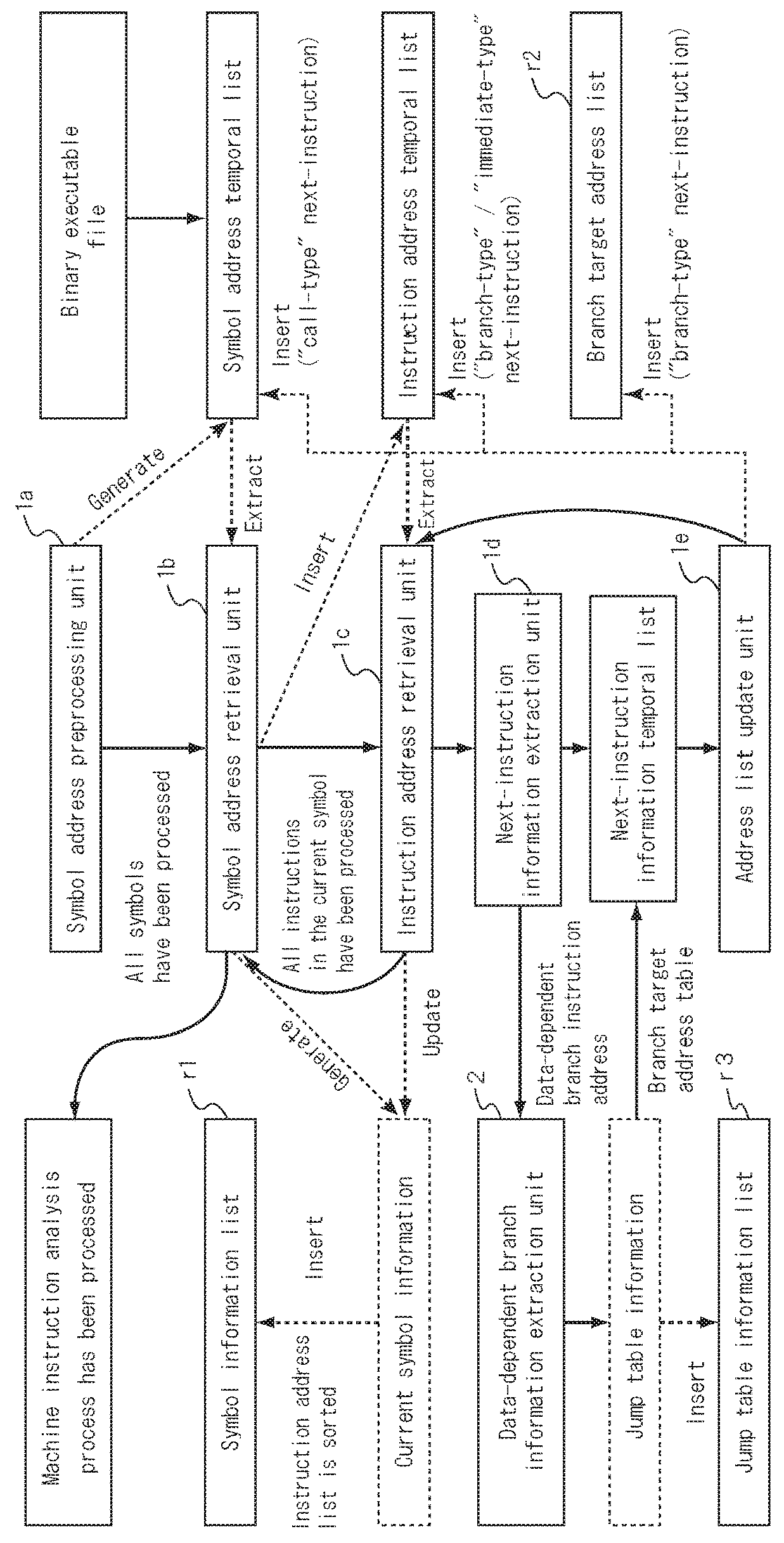
[0320]Machine instruction analysis unit 1 is composed of
[0321]a symbol address preprocessing unit 1a,
[0322]symbol address retrieval unit 1b,
[0323]instruction address retrieval unit 1c,
[0324]next-instruction information extraction unit 1d,
[0325]address list update unit 1e, and
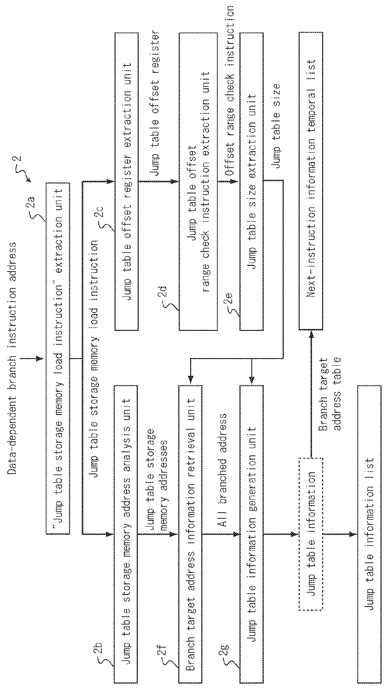
[0326]data-dependent branch information extraction unit 2.
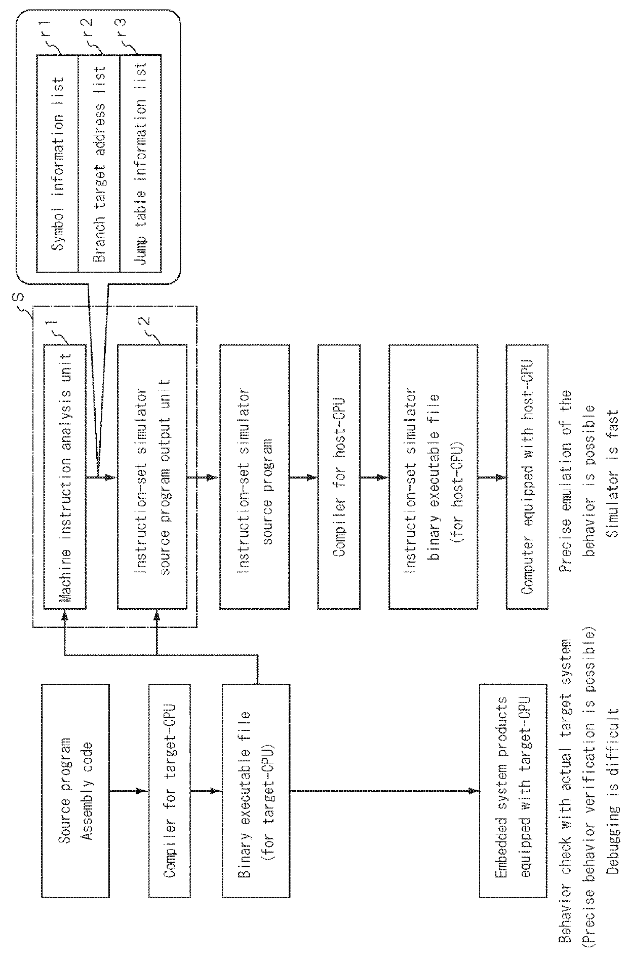
[0327]Machine instruction analysis unit 1, in order to generate the C code from the analyzed machine instruction, outputs a symbol information list r1, branch target address list r2 and jump table infor...
example 1
OF MACHINE INSTRUCTION ANALYSIS PROCESS (ARMv5 INSTRUCTION-SET)
[0393]FIG 10 shows the machine instructions and assembly instructions of ARMv5 instruction-set on the jump_test function In FIG. 8. Each line shows the instruction address (hexadecimal format), machine instruction data (hexadecimal format) and assembly instruction, along with the instruction type in the case the instruction modifies the program counter. In the following explanations, it is assumed that the address 0x8340 of the function “jump_test” is retrieved from the “symbol address temporal list”, and the succeeding machine instruction analysis process is explained thereafter.
[0394]Table 1 shows the machine instruction analysis process between 0x8340-0x834c.
TABLE 1Machine instruction analysis process between 0x8340-0x834cUnitProcess overviewUpdated information, list etc.Symbol address retrievalRetrieve 0x8340Current symbol address: 0x8340unit 1bInstruction address list of the currentsymbol: {empty}Instruction address...
example 2
OF MACHINE INSTRUCTION ANALYSIS PROCESS (x86(64-BIT) INSTRUCTION-SET)
[0415]FIG. 11 shows the machine instructions and assembly instructions of x86(64-bit) instruction-set on the jump_test function in FIG. 8. Each line shows the instruction address (hexadecimal format in six digits), machine instruction data (hexadecimal format delimited by two digits in the order from left to right) and assembly instruction, along with the instruction type in the case the instruction modifies the program counter.
[0416]In the following explanations, it is assumed that the address 0x400560 of the function “jump_test” is retrieved from the “symbol address temporal list” by the symbol address retrieval unit 1b, and the succeeding machine instruction analysts process is explained thereafter.
[0417]Table 7 shows the process of the machine instruction analysis unit 1 of jump_test function in FIG. 11 between 0x400560-0x40056e.
TABLE 7Machine instruction analysis process between 0x400560-0x40056eUnitProcess ov...
PUM
 Abstract
Description
Claims
Application Information