Data Centre Cooling System

a cooling system and data centre technology, applied in cooling/ventilation/heating modifications, electrical equipment, support structure mounting, etc., can solve the problems of increasing the amount of energy required to drive air through the system, affecting the cooling capacity of the idaho, and unable to supply the cold aisles with sufficient cooling air. , to achieve the effect of reducing the temperature of air, avoiding the air inside the data centre building, and increasing the cooling capacity of the idah

Active Publication Date: 2018-06-14
BRIPCO
View PDF0 Cites 14 Cited by
  • Summary
  • Abstract
  • Description
  • Claims
  • Application Information

AI Technical Summary

Benefits of technology

[0104]The present invention also provides, according to a fourth aspect, a method of cooling electronic equipment in a data centre building. The method may comprise a step of providing and then operating an IDAHU according to the first and / or second aspect of the invention, and / or a data centre according to the third aspect of the invention. Preferably, the method comprises adding a controlled amount of external air from outside the data centre into the data centre building. Optionally, the method comprises providing an operating at least one air handling unit (AHU) separate from the IDAHU, as described with reference to the third aspect of the invention above. It will be appreciated that the air inside the data centre building is the internal air circulated around the data centre building to cool the items of electronic equipment housed in the data centre. Preferably, the volume of external air added to the air inside the data centre building per hour is between a quarter and double the volume of air inside the data centre building, for example the method comprises admitting approximately the same volume of external air from outside the data centre building into the data centre building as the volume of the air circulating inside the data centre building every hour. In other words, the method comprises replacing the air inside the data centre building every 0.5 to 4 hours, preferably approximately every hour. It will be appreciated that replacing the air inside the data centre building every 0.5 to 4 hours avoids the air inside the data centre building becoming stale. Preferably the method comprises filtering and / or adjusting the temperature and / or humidity of the external air admitted into the data centre building.
[0105]Preferably, the method comprises controlling the volume of air moved along the external air flow path, for example by controlling the speed of fans of the IDAHU provided in the external air flow path, in dependence on the temperature of air exiting the internal air flow path of the IDAHU. It will be appreciated that one approach to lowering the temperature of air exiting the internal air flow path (i.e. the air being used to cool the items of IT equipment) may be to increase the amount of air from outside the data centre building being contacted with the sections of heat tubes located in the external air flow path, thereby increasing the cooling capacity of the IDAHU.

Problems solved by technology

If the volume is not sufficient, then the servers can be starved of cooling air or draw in warm air from other areas of the data centre, possibly resulting in the IT equipment overheating.
In a traditional data centre in which cooling air is supplied to the cold aisles via an underfloor plenum, it can be difficult to supply the cold aisles with a sufficient volume of cooling air at a given temperature because of the comparatively small cross-sectional area of the underfloor plenum.
Furthermore, such underfloor plenums typically have a high air-flow resistance due to their small size, tight corners and the need to force air through perforated floor tiles, thus increasing the amount of energy required to drive air through the system.
A disadvantage of such ‘free-air’ cooling methods is that the outside air must be carefully filtered and treated to avoid bringing contaminants such as particulates into the data centre, which contaminants may damage the servers.
It will be appreciated that such a system is relatively complex to operate and remains vulnerable to ingress of contaminated air if detection equipment is deficient or if the time taken for the system to switch mode is too long.
A disadvantage of such a system is the relatively high resistance to airflow through the heat exchanger tubes.
A problem associated with known data centre cooling systems using heat exchangers is how to achieve close control of the cooling capacity.
It will be appreciated that although it may be desirable to increase the cooling capacity of the heat exchanger by, for example, spraying the parts of the heat exchanger in contact with the external air flow with a fluid (such as water) which evaporates into the external air stream, it is nevertheless costly and inefficient to run such sprayers when they are not needed.
Furthermore, introducing substantial quantities of liquid coolant into the system in this way may lead to a degradation of components, for example due to corrosion by the fluid itself or by damage caused by contaminants in the fluid.
It will be appreciated that such an approach is wasteful, both in terms of the data centre footprint (data centre air handling units are typically large, occupying many hundreds of square feet) and in terms of the cost of duplicating all air handling components.
Often, this approach is particularly wasteful because only a limited number of the air handler components are prone to failure or require maintenance.
The latter requirement is particularly challenging for the heat exchange elements (such as heat tubes) of an indirect air handling unit.

Method used


Image

  • Data Centre Cooling System
  • Data Centre Cooling System
  • Data Centre Cooling System

Examples


first embodiment

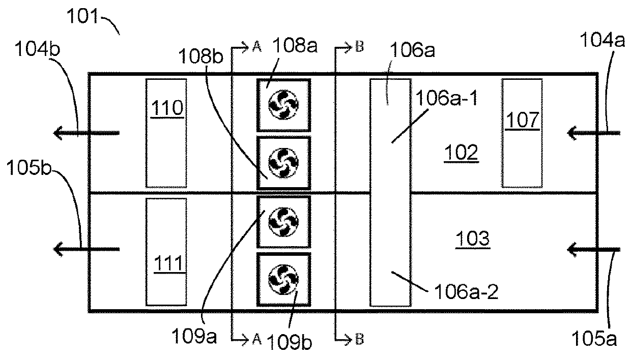
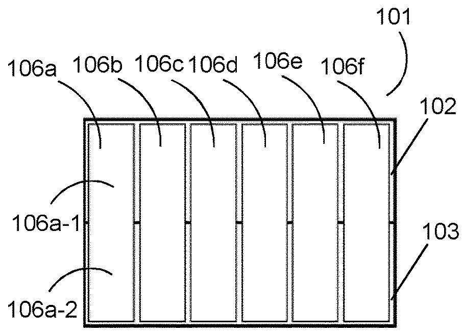
[0181]FIG. 1 shows schematically a sectional side elevation of an Indirect Air Handling Unit (IDAHU) 101. The IDAHU 101 comprises an external air flow path 102 and a separate internal air flow path 103. The external air flow path 102 is arranged to be in fluid communication with air outside the data centre such that, in use, external air enters the external air flow path 102 as shown by arrow 104a and is returned to outside the data centre as shown by arrow 104b. The internal air flow path 103 is arranged to be in fluid communication with air inside the data centre such that, in use, internal air enters the internal air flow path 103 as shown by arrow 105a and is returned to the inside of the data centre as shown by arrow 105b. The IDAHU 101 comprises a plurality of heat tubes arranged in a plurality of heat tube panels 106 (only one heat tube panel, 106a is shown in FIG. 1, heat tube panels 106b to 106f are shown in FIG. 3), each heat tube panel having a first section extending int...

second embodiment

[0185]FIG. 4 shows a sectional side elevation of an IDAHU 201. IDAHU 201 comprises an upper deck 202 that defines an external air flow path positioned above a lower deck 203 that defines an internal air flow path, the external and internal air flow paths being horizontal. In use, external air enters the external air flow path as shown by arrows 204a, and exits the external air flow path as shown by arrows 204b. Internal air enters the internal air flow path as shown by arrows 205a and flows along the internal air flow path parallel to the flow of external air flowing along the external air flow path, but in the opposite direction, and then exits the internal air flow path as indicated by arrows 205b. IDAHU 201 is a modular IDAHU, comprising a plurality of external air flow path modules, a plurality of internal air flow path modules and a plurality of heat tube modules (each of which define a section of the internal air flow path and a section of the external air flow path.

[0186]Modu...

third embodiment

[0190]FIG. 4a shows a sectional side elevation of an IDAHU 2011. IDAHU 2011 is a module IDAHU with a similar but more compact arrangement of modules as provided in the IDAHU 201 of FIG. 4. The IDAHU 2011 comprises upper and lower decks 2021, 2031 defining horizontal external and internal air flow paths. Arrows 2041a, 2041b show external air entering and exiting the external air flow path, and arrows 2051a, 2051b show internal air entering and exiting the internal air flow path.

[0191]Modular IDAHU 2011 comprises: a heat tube module 2311 defining sections of the internal and external air flow paths; a humidification module 2121 positioned immediately upstream of the heat tube module 2311 in the external air flow path, the humidification module 2121 comprising filters 2111 at its upstream end; external fan module 2131 positioned immediately downstream of the heat tube module 2311 in the external air flow path; DX condenser coil module 2141 positioned immediately downstream of the exter...


PUM


Abstract

An air handling unit for a data centre, a data centre comprising such a unit, a method of operating such a unit and a method of cooling IT equipment in a data centre using such a unit is disclosed. An indirect air handling unit (IDAHU) (101) for a data centre comprises an external air flow path (102) arranged to be in fluid communication with air outside the data centre; an internal air flow path (103) arranged to be in fluid communication with air inside the data centre, wherein the external air flow path (102) is separated from the internal air flow path (103); and a plurality of heat tube panels (106). Preferably, each heat tube panel (106) comprises at least one heat tube, wherein each heat tube comprises a first section extending into the external air flow path (102) and a second section extending into the internal air flow path (103). Preferably, the plurality of heat tube panels (106) is arranged in at least one row across the internal air flow path (103) and across the external air flow path (102). Preferably, at least one of the heat tube panels (106) is a removable heat tube panel that extends through an opening between the internal air flow path (103) and the external air flow path (102).

Description

FIELD OF THE INVENTION[0001]The present invention concerns air handling units for data centres and methods of cooling a data centre. More particularly, but not exclusively, this invention concerns indirect air handling units for use in data centres and methods of cooling a data centre using an indirect air handling unit.BACKGROUND OF THE INVENTION[0002]A data centre is a late 20th Century development that has grown as a response to the increasing demand for computer processing capability and a recognition of the importance of IT in the place of every business and organisation today. Whereas smaller organisations have sufficient processing power with laptops, PCs and occasionally servers, larger organisations require higher capacity centralised processing to serve a wide range of needs and applications. A few years ago this capacity was supplied by large mainframe computers, but more recently the method used has been to provide data centres comprising many networked computer servers ...

Claims


Application Information

Patent Timeline
Patent Type & Authority Applications(United States)
IPC IPC(8): H05K7/20
CPCH05K7/20745H05K7/20145H05K7/1488
Inventor EDGE, ADRIANTHORNTON, WILLIAM
Owner BRIPCO
Why Eureka
Try Eureka