
Vehicle steering system and lane keeping system

Active Publication Date: 2018-06-21
MITSUBISHI ELECTRIC CORP
View PDF4 Cites 5 Cited by
  • Summary
  • Abstract
  • Description
  • Claims
  • Application Information

AI Technical Summary

Benefits of technology

The patent describes a vehicle steering system that allows for smooth control-switching when the driver returns to the target traveling line after completing a steering override. This means that even after the driver has taken control and temporarily decreased the amount of steering, the system can smoothly return to the original target without causing any sudden increase in the steering control amount.

Problems solved by technology

However, in the conventional techniques disclosed in Japanese Patent Application Laid-Open Nos. 2015-13545 and 2005-67484, when the driver deviates from the target traveling line and performs steering intervention, i.e., so-called override, in which the driver operates the steering wheel so as to avoid other vehicles, obstacles, and the like on the target traveling line, large steering assist force is instantaneously generated for canceling the deviation from the target traveling line due to the override, and interferes with the driver's steering intervention, thereby causing a problem that the operation of avoiding other vehicles, obstacles, and the like is inhibited.
However, after the decrease in the control amount due to the driver's steering intervention and immediately after completion of the steering intervention, that is, immediately after completion of the override, the control amount abruptly increases, thereby causing a problem that, in some cases, the vehicle fluctuates at the time of control-switching and smooth control-switching cannot be performed.

Method used


Image

  • Vehicle steering system and lane keeping system
  • Vehicle steering system and lane keeping system
  • Vehicle steering system and lane keeping system

Examples


first preferred embodiment

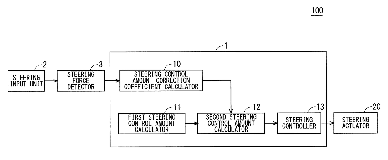
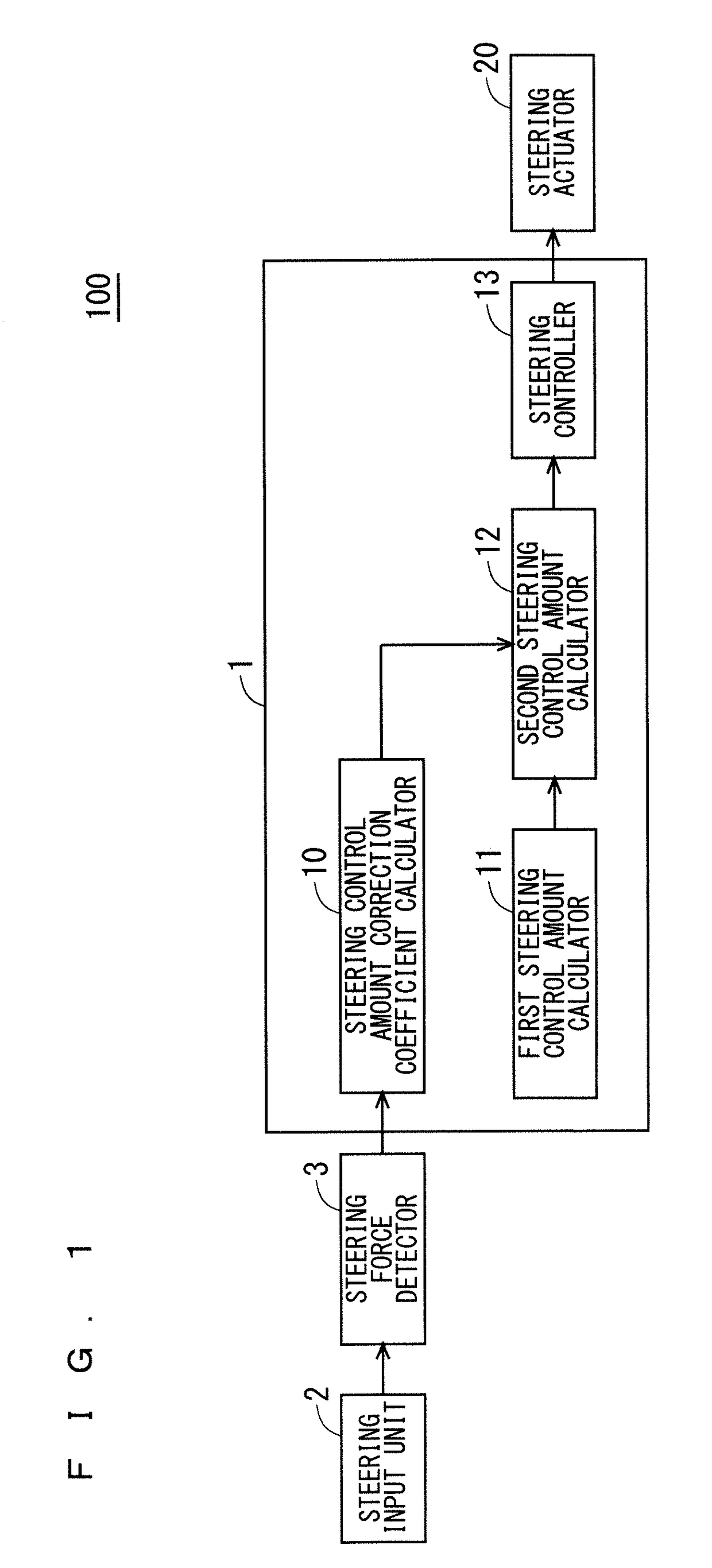
[0029]FIG. 1 is a functional block diagram illustrating a configuration of a vehicle steering system 100 of a first preferred embodiment according to the present invention. As illustrated in FIG. 1, a vehicle steering system 100 includes a vehicle steering device 1 (hereinafter may be referred to as “steering device 1”), a steering input unit 2, steering force detector 3, and a steering actuator 20. In the following description, a vehicle mounted with the steering device 1 will be referred to as a “subject vehicle”.

[0030]The steering input unit 2 is a steering wheel with which the driver steers the vehicle. Note that the steering input unit 2 may be a joystick for steering the vehicle or switches for selecting the steering, and its format is not limited.

[0031]The steering force detector 3 is, for example, a torque sensor, connected to the steering input unit 2, detects steering force which is an amount of operation on the steering input unit 2 by the driver, and transmits the steeri...

second preferred embodiment

[0097]FIG. 14 is a functional block diagram illustrating a configuration of a vehicle steering system 200 according to a second preferred embodiment of the present invention. As illustrated in FIG. 14, the vehicle steering system 200 further includes, in the vehicle steering system 100 of the first preferred embodiment, a vehicle state quantity detector 4 for detecting the vehicle state quantity of the subject vehicle. The detection result by the vehicle state quantity detector 4 is input into the second steering control amount calculator 12.

[0098]The vehicle state quantity detector 4 detects the vehicle state quantity of the subject vehicle. Examples of the vehicle state quantity include a steering angle, a yaw rate, a lateral acceleration, and a road surface reaction torque, but the vehicle state quantity is not limited thereto. In the vehicle steering system 100 of the first preferred embodiment, the first steering control amount calculator 11 calculates the vehicle state quantit...

application example

to Lane Keeping System

[0107]The vehicle steering system according to the first and second preferred embodiments described above can be applied to a lane keeping system. FIG. 15 is a functional block diagram illustrating a configuration of a lane keeping system 300 to which the vehicle steering system 100 of the first preferred embodiment is applied. As illustrated in FIG. 15, the lane keeping system 300 further includes, in the vehicle steering system 100 of the first preferred embodiment, a target traveling line setter 6 that sets a target traveling line for a vehicle to travel following a traveling road, and a traveling road recognizer 7 that recognizes the traveling road on which the vehicle travels, and the recognition result by the traveling road recognizer 7 is input into the target traveling line setter 6.

[0108]The traveling road recognizer 7 detects right and left white lines of the subject vehicle based on a video signal output from a device that captures a forward image, s...


PUM


Abstract

A vehicle steering system includes: a steering input unit that is steered by a driver; a steering force detector to detect steering force input into the steering input unit; a first steering control amount calculator to calculate a first steering control amount for bringing the vehicle close to the target traveling line; a steering control amount correction coefficient calculator to calculate a steering control amount correction coefficient for correcting a steering control amount based on the steering force; a second steering control amount calculator to calculate a second steering control amount based on the first steering control amount and the steering control amount correction coefficient; and a steering controller that steers and controls the vehicle based on the second steering control amount.

Description

BACKGROUND OF THE INVENTIONField of the Invention[0001]The present invention relates to a vehicle steering system, and particularly relates to a vehicle steering system for assisting steering of a steering wheel such that a vehicle travels following a desired target traveling line.Description of the Background Art[0002]There has hitherto been known a technique of assisting steering of a steering wheel or performing automatic steering such that a vehicle travels following a desired target traveling line.[0003]For example, as disclosed in Japanese Patent Application Laid-Open No. 2015-13545, there is a technique of recognizing a white line on a road by using a camera attached to the front of a vehicle, to perform steering control such that the vehicle travels at the center of a lane. This is called a lane keeping system.[0004]Further, as disclosed in Japanese Patent Application Laid-Open No. 2005-67484, there is a technique of calculating a target trajectory by obtaining a subject veh...

Claims


Application Information

Patent Timeline
IPC IPC(8): B62D15/02B60W30/12
CPCB62D15/025B60W30/12B62D6/002B62D6/008
Inventor SHIROZONO, MASATAKANAKAJIMA, SHUNSUKEHORI, YASUYOSHI
Owner MITSUBISHI ELECTRIC CORP
Learn More