Light modulation film and method for manufacturing same, and light modulation element

a technology of light modulation film and manufacturing method, which is applied in the direction of optical elements, instruments, vacuum evaporation coating, etc., can solve the problems of deterioration of switching characteristics, and achieve the effect of excellent light modulation performan

Active Publication Date: 2018-06-21
NITTO DENKO CORP
View PDF0 Cites 2 Cited by
  • Summary
  • Abstract
  • Description
  • Claims
  • Application Information

AI Technical Summary

Benefits of technology

[0018]In a light modulation film of the present invention, an oxidized region existing at the interface on the film substrate side of the light modulation layer has an action of blocking an oxidizing gas from a polymer film substrate. Thus, oxidation of a light modulation region at the interface on the catalyst layer side of the light modulation layer is suppressed, so that excellent light modulation performance can be exhibited.

Problems solved by technology

For the hydrogen-activation-type light modulation material, it is known that when switching between a transparent state by hydrogenation and a reflection state by dehydrogenation is repeated, switching characteristics may be deteriorated because magnesium in a magnesium alloy in a light modulation layer passes through a catalyst layer, and is deposited on the surface, and oxidized.

Method used


Image

  • Light modulation film and method for manufacturing same, and light modulation element
  • Light modulation film and method for manufacturing same, and light modulation element
  • Light modulation film and method for manufacturing same, and light modulation element

Examples


example 1

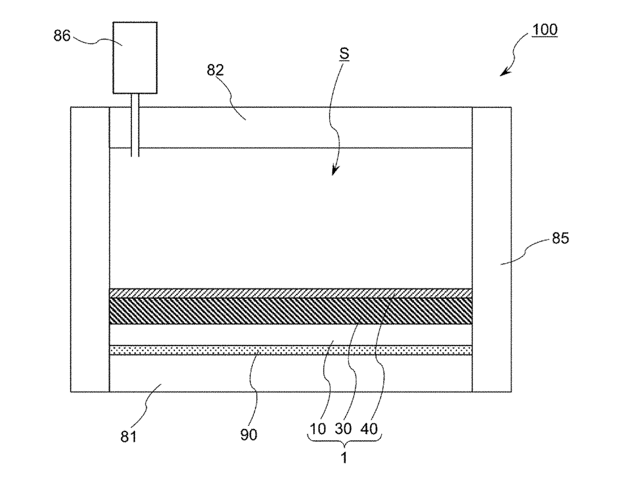
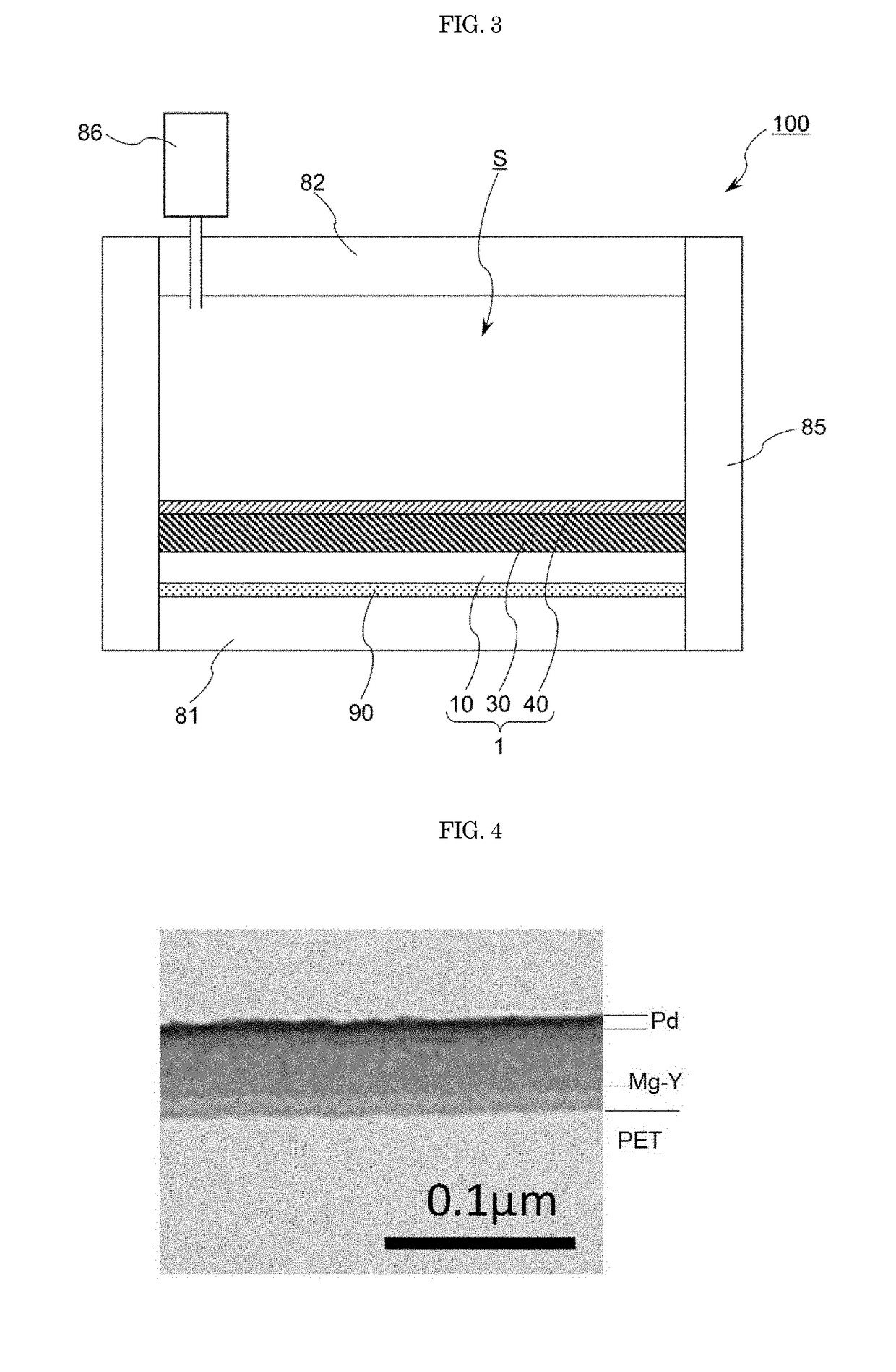
[0077]A roll of a 188 μm-thick polyethylene terephthalate (PET) film (manufactured by Mitsubishi Plastics, Inc.) was set in a roll-to-roll sputtering apparatus, and the inside of a sputtering apparatus was evacuated until the ultimate vacuum degree reached 5×10⁻³ Pa. The PET film substrate was conveyed in the sputtering apparatus without introducing a sputtering gas, and as a result, the internal pressure of the apparatus increased to 4×10⁻² Pa. This is because residual gas contained in the PET film was released into the sputtering apparatus.

[0078]Thereafter, a sputtering gas was introduced into the sputtering apparatus, and a light modulation layer including an Mg—Y alloy and a catalyst layer including Pd were sequentially deposited while the film substrate was run on a deposition roll.

[0079]An Mg—Y split target (manufactured by RARE METALLIC Co., Ltd.) having an Mg metal plate and a Y metal plate at an erosion portion area ratio of 2:5 was used for deposition of the Mg—Y alloy lay...

example 2

[0081]Except that the ultimate vacuum degree before the start of sputtering deposition was 8×10⁻⁴ Pa, the same procedure as in Example 1 was carried out to prepare a light modulation film.

example 3

[0082]Except that the conditions for deposition of the light modulation layer were changed as described below, the same procedure as in Example 1 was carried out to prepare a light modulation film. In deposition of an Mg—Y alloy layer, first the Mg—Y alloy layer was formed in a thickness of 25 nm under 0.4 Pa vacuum environment in which 5% of oxygen in terms of a flow rate was introduced in argon as a sputtering gas. Subsequently, an Mg—Y alloy layer was formed in a thickness of 40 nm under an environment at 0.4 Pa with only argon introduced as a sputtering gas.


PUM

PropertyMeasurementUnit
thicknessaaaaaaaaaa
thicknessaaaaaaaaaa
thicknessaaaaaaaaaa

Abstract

A light modulation film (1) includes a light modulation layer (30) whose state is reversibly changed between a transparent state by hydrogenation and a reflective state by dehydrogenation, and a catalyst layer (40) that promotes hydrogenation and dehydrogenation in the light modulation layer, in this order on a polymer film substrate (10). In a thickness-direction distribution of an element concentration as measured by X-ray electron spectroscopy, the light modulation layer (30) includes a light modulation region (32) with an oxygen content of 50 atom % or more and having a thickness of 10 nm or more on a catalyst layer (40)-side, and an oxidized region (31) with an oxygen content of less than 50 atom % on a polymer film substrate (10)-side.

Description

TECHNICAL FIELD[0001]The present invention relates to a light modulation film which is used for a hydrogen-activation-type light modulation element capable of switching between a transparent state and a reflective state by hydrogenation and dehydrogenation, and a method for manufacturing the light modulation film. The present invention also relates to a light modulation element including the light modulation film.BACKGROUND ART[0002]Light modulation elements are used for window panes of buildings and vehicles, interior materials, and the like. Particularly in recent years, demand and expectation for light modulation elements have been increased from the viewpoints of reducing a cooling and heating load, reducing a lighting load, improving comfort, and so on.[0003]As the light modulation element, the following systems have been developed: an electric field drive system in which a liquid crystal material or an electrochromic material is used, and the light transmittance is controlled ...

Claims


Application Information

Patent Timeline
Patent Type & Authority Applications(United States)
IPC IPC(8): G02F1/19
CPCG02F1/19G02B5/26C23C14/0036C23C14/082C23C14/205C23C14/562C23C14/34
Inventor KATAGIRI, MASAYOSHIFUJINO, NOZOMINASHIKI, TOMOTAKE
Owner NITTO DENKO CORP
Why Eureka
Try Eureka