Surface treatment device

a surface treatment and device technology, applied in the field of surface treatment devices, can solve the problems of generating harmful compounds, severe allergic reactions, and less effective capture of larger micro-particles, and achieve the effect of effective neutralization of surface allergens, effective neutralization of such surface allergens, and higher air flow velocity

Inactive Publication Date: 2018-07-05
KONINKLJIJKE PHILIPS NV
View PDF5 Cites 8 Cited by
  • Summary
  • Abstract
  • Description
  • Claims
  • Application Information

AI Technical Summary

Benefits of technology

[0011]According to an embodiment of the invention, the air flow generator is configured to generate a net air flow velocity of 1 m / s or less. It has been surprisingly found that by guiding an air flow from the surface into the surface treatment device at such low velocities, an effective neutralization of surface allergens, i.e. micro-particles such as pollen or micro-organisms such as (dust) mites can be achieved without producing levels of side products such as ozone and NO2 that are harmful. This compares favorably to e.g. plasma generating air purifiers than typically operate air flows in excess of 100 m3 / hour, which corresponds to much higher air flow velocities, making air purifiers substantially noisier than the surface treatment device of the present invention. Effective neutralization of such surface allergens can be achieved by treating a surface area under treatment for a short period of time only, i.e. no more than several seconds, thus making the surface treatment device easy to use. Moreover, the low air velocity ensures low power consumption of the surface treatment device, which is desirable in terms of reducing the carbon foot print as well compliance with regulations designed to enforce such reduction.
[0012]According to an embodiment of the invention, the air flow generator is adapted such that the air flow is in the range of 0-10 m3 / hour. For example, the air inlet may have an inlet area such that a net surface air flow through the air inlet is in the range of 0-10 m3 / hour. This is substantially lower than the air flow through an air purifier for instance, which therefore translates to a substantial reduction in generation of harmful side products.
[0013]In a particularly advantageous embodiment, the net surface air flow is zero. In this embodiment, air turbulence may be created at the surface to be treated, with the reactive particles injected into the turbulent air to neutralize surface allergens at the surface. The higher velocity of the reactive particles compared to the net air flow velocity ensures that the reactive particles can travel opposite to the direction of the net air flow and can penetrate the surface to be treated, e.g. a carpet, soft furnishing, mattress and so on, to effectively neutralize surface allergens without requiring a net surface air flow. In an embodiment, the air inlet and the air outlet are located such that a net air flow at the surface is zero.
[0014]The reactive particles generator may for instance be an ionization device or a plasma generator. Particularly preferred is a dielectric barrier discharge plasma generator or a corona discharge generator. A corona discharge generator may further act as (part of) the air flow generator by generating ionic wind resulting from the corona discharge. In such an embodiment the corona discharge device has a double functionality. Its first function is to generate the air flow from the air inlet to the air outlet. Its second function is to generate reactive particles, e.g. plasma, from air. Thus, by using a corona discharge device, only a single component is needed for generating air flow and reactive particles instead of two separate components as disclosed by the prior documents. This obviates the need for additional components in the surface treatment device, thus reducing its cost.
[0017]Preferably, the surface treatment device further comprises an ozone neutralizing element in the air flow, such as in the conduit between the reactive particles generator and the air outlet or in the air outlet. The ozone element may be located downstream from the reactive particles generator. An example of such an ozone neutralizing element is an active carbon containing element. As active carbon reacts with ozone, this further reduces the amount of ozone produced by the surface treatment device. Alternatively, catalysts that decompose ozone may be used in the ozone neutralizing element.
[0020]In an embodiment, the surface treatment device comprises a removable head including the air inlet and the reactive particle generator. This allows for the surface treatment device to be operated without the reactive particle generator, e.g. by using a different head as well as for replacement of the reactive particle generator by providing a replacement head, thus obviating the need to replace the entire surface treatment device in case of a reactive particle generator reaching its end of life.

Problems solved by technology

Air purifiers are particularly effective in capturing gaseous compounds and particles such as PM 2.5 particles but are less effective in capturing larger micro-particles, such as pollen particles, as the weight of such particles typically causes such particles to precipitate on surfaces, where they can cause severe allergic reactions, e.g. asthmatic attacks in children playing in contact with such surfaces.
Other harmful allergens include micro-organisms, e.g. dust-dwelling micro-organisms such as mites, which may be particularly problematic in bedding, e.g. pillows, duvets, blankets and mattresses.
However, such plasma generation causes the generation of harmful compounds as side products, such as ozone (O3) and NO2.

Method used


Image

  • Surface treatment device
  • Surface treatment device
  • Surface treatment device

Examples


Embodiment Construction

[0040]It should be understood that the Figures are merely schematic and are not drawn to scale. It should also be understood that the same reference numerals are used throughout the Figures to indicate the same or similar parts.

[0041]Throughout the description reference is made to “reactive particles”. This may refer to plasma or another substance that can disinfect particles such as allergens.

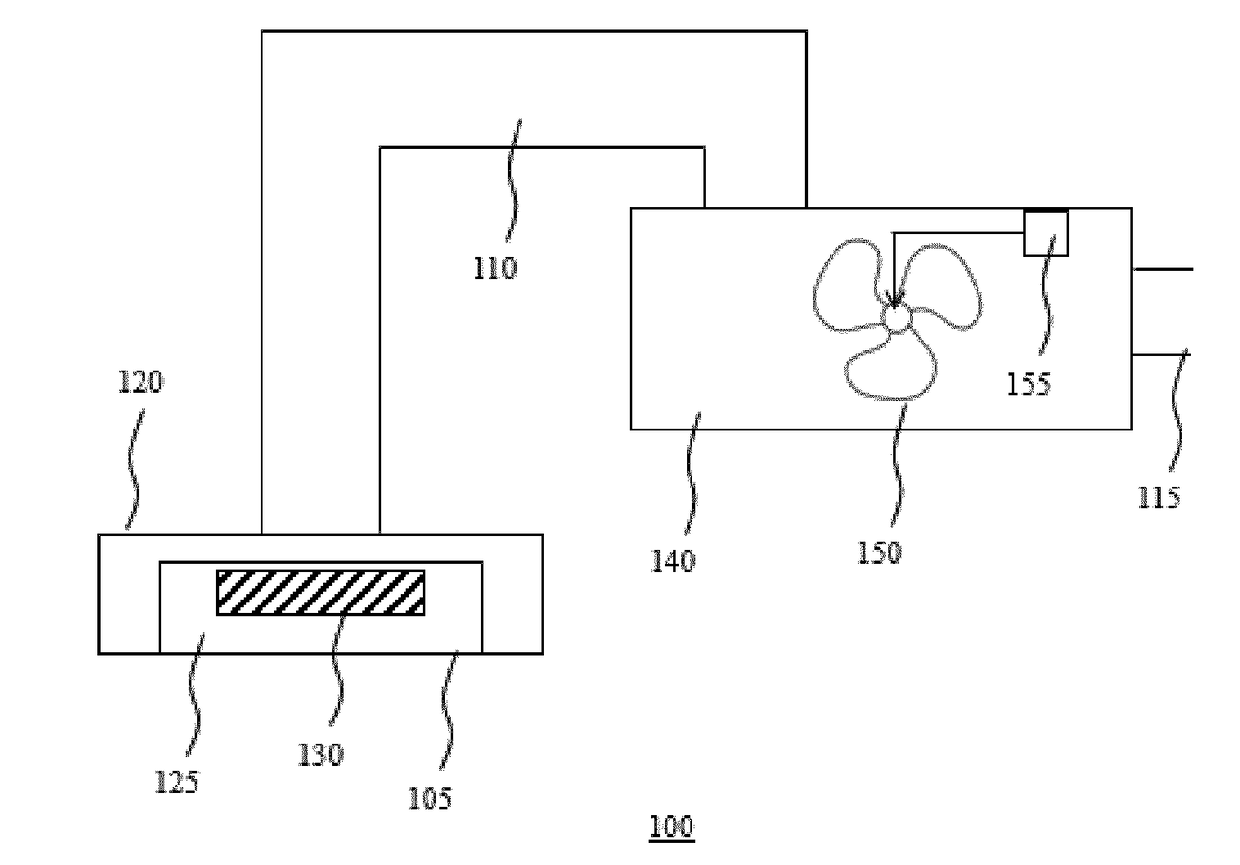
[0042]FIG. 1 schematically depicts a surface treatment device 100 according to an embodiment. The surface treatment device 100 comprises a conduit 110 located in between an air inlet 105 and an air outlet 115 and includes an air flow generator 150 for generating an air flow from the inlet 105 to the outlet 115. The conduit typically includes an enclosure or treatment chamber 125 in which a reactive particles generator 130 such as an ionization device or a plasma generating device is located. The plasma generating device typically is a non-thermal plasma generating device and employs a dielectr...


PUM

PropertyMeasurementUnit
air flow velocityaaaaaaaaaa
velocityaaaaaaaaaa
thicknessaaaaaaaaaa

Abstract

A surface treatment device (100) is disclosed that comprises a conduit (110) including an air inlet (105) and an air outlet (115). The conduit comprises a reactive particles generator (130) for generating reactive particles from air and arranged to subject the surface to the generated reactive particles. The reactive particles generator (130) is also used for generating an air flow from the air inlet to the air outlet through the conduit.

Description

FIELD OF THE INVENTION[0001]The present invention relates to treating a surface contaminated with micro-particles such as pollen and / or micro-organisms such as mites.BACKGROUND OF THE INVENTION[0002]Air purification devices are commonly employed to filter air in closed environments, e.g. in domestic or commercial dwellings. Such air purification serves a number of purposes, e.g. odor control and allergen filtration from the treated air. Air purifiers are particularly effective in capturing gaseous compounds and particles such as PM 2.5 particles but are less effective in capturing larger micro-particles, such as pollen particles, as the weight of such particles typically causes such particles to precipitate on surfaces, where they can cause severe allergic reactions, e.g. asthmatic attacks in children playing in contact with such surfaces. Other harmful allergens include micro-organisms, e.g. dust-dwelling micro-organisms such as mites, which may be particularly problematic in beddi...

Claims


Application Information

Patent Timeline
Patent Type & Authority Applications(United States)
IPC IPC(8): A61L2/14A61L2/26A47L7/00
CPCA61L2/14A61L2/26A47L7/0085A61L2202/11A47L9/02A47L11/405A47L2201/00
Inventor RONDA, CORNELIS REINDERJACOBS, JEAN-PAULSUIJVER, JAN FREDERIKCHEN, WEIZHONGBLEEKER, JEAN BARTVAN DER GRAAF, TIMOTHYMARRA, JOHANKOERBER, ACHIM GERHARD ROLFHILBIG, RAINER
Owner KONINKLJIJKE PHILIPS NV
Why Eureka
Try Eureka