Sliding component

a technology of sliding components and sliding faces, which is applied in the direction of mechanical equipment, machines/engines, liquid fuel engines, etc., can solve the problems of not taking the necessary measures to prevent the generation of a deposit on the sliding face, and achieve the effect of preventing the generation of a deposit in the fluid circulation groove and reliably generating the pressure differen

Active Publication Date: 2018-07-05
EAGLE INDS
View PDF14 Cites 1 Cited by
  • Summary
  • Abstract
  • Description
  • Claims
  • Application Information

AI Technical Summary

Benefits of technology

[0013]The present invention has the following excellent effects.
[0014](1) The sliding face of the stationary-side seal ring is provided with the fluid circulation groove which communicates with the high-pressure fluid side via the entrance portion and the exit portion and is separated from the low-pressure fluid side by the land portion. The rotating-side seal ring is formed to have a larger outer diameter and a smaller diameter than the stationary-side seal ring. The at least one groove into which the claw of the rotational force transmission member for transmitting the rotational force of the rotating shaft loosely fits is provided on the outer periphery of the rotating-side seal ring. The width of the at least one groove in the circumferential direction is smaller than the length in the circumferential direction between the entrance portion and the exit portion of the fluid circulation groove. WMR / WSR is set within a range of 0.75<WMR / WSR<1.4, where WMR is the face width defined between the inner diameter of the at least one groove of the rotating-side seal ring and the inner diameter of the sliding face of the stationary-side seal ring and WSR is the face width of the sliding face of the stationary-side seal ring, Accordingly, the pressures at the entrance portion and the exit portion of the fluid circulation groove constantly fluctuate such that one is higher or smaller than the other, and the fluid in the fluid circulation groove repeatedly moves. Therefore, even in a case in which the sealed fluid includes the deposit generation causing substance, it is possible to prevent the generation of a deposit in the fluid circulation groove, thereby maintaining the sealing function of the sliding face over a long period.
[0015](2) The at least one groove includes a plurality of grooves, and the plurality of grooves are provided such that, when one of the grooves is positioned opposite the entrance portion of the fluid circulation grooves, the other grooves are not positioned opposite the exit portion of the fluid circulation groove. Accordingly, it is possible to greatly and reliably generate the pressure difference between the entrance portion and the exit portion of the fluid circulation groove, and therefore, it is possible to further prevent the generation of a deposit in the fluid circulation groove.

Problems solved by technology

In the conventionally known mechanical seals, in order to prevent the occurrence of wear and burning due to frictional heat generation on the sliding face, a groove is formed on the sliding face such that a fluid layer is formed between the sliding faces (for example, refer to Patent Documents 1, 2, and 3); however, these inventions relate to introducing a fluid to the sliding face, and in these inventions, measures have not been taken to prevent the generation of a deposit on the sliding face.

Method used


Image

  • Sliding component
  • Sliding component
  • Sliding component

Examples


first embodiment

[0020]A description will be given of a sliding component according to a first embodiment of the present invention, with reference to FIGS. 1 and 2.

[0021]In this embodiment, the description will be given exemplifying a mechanical seal which is an example of a sliding component. The outer peripheral side of the slide component which configures the mechanical seal will be described as a high-pressure fluid side (a sealed fluid side) and the inner peripheral side thereof as a low-pressure fluid side (a gas side).

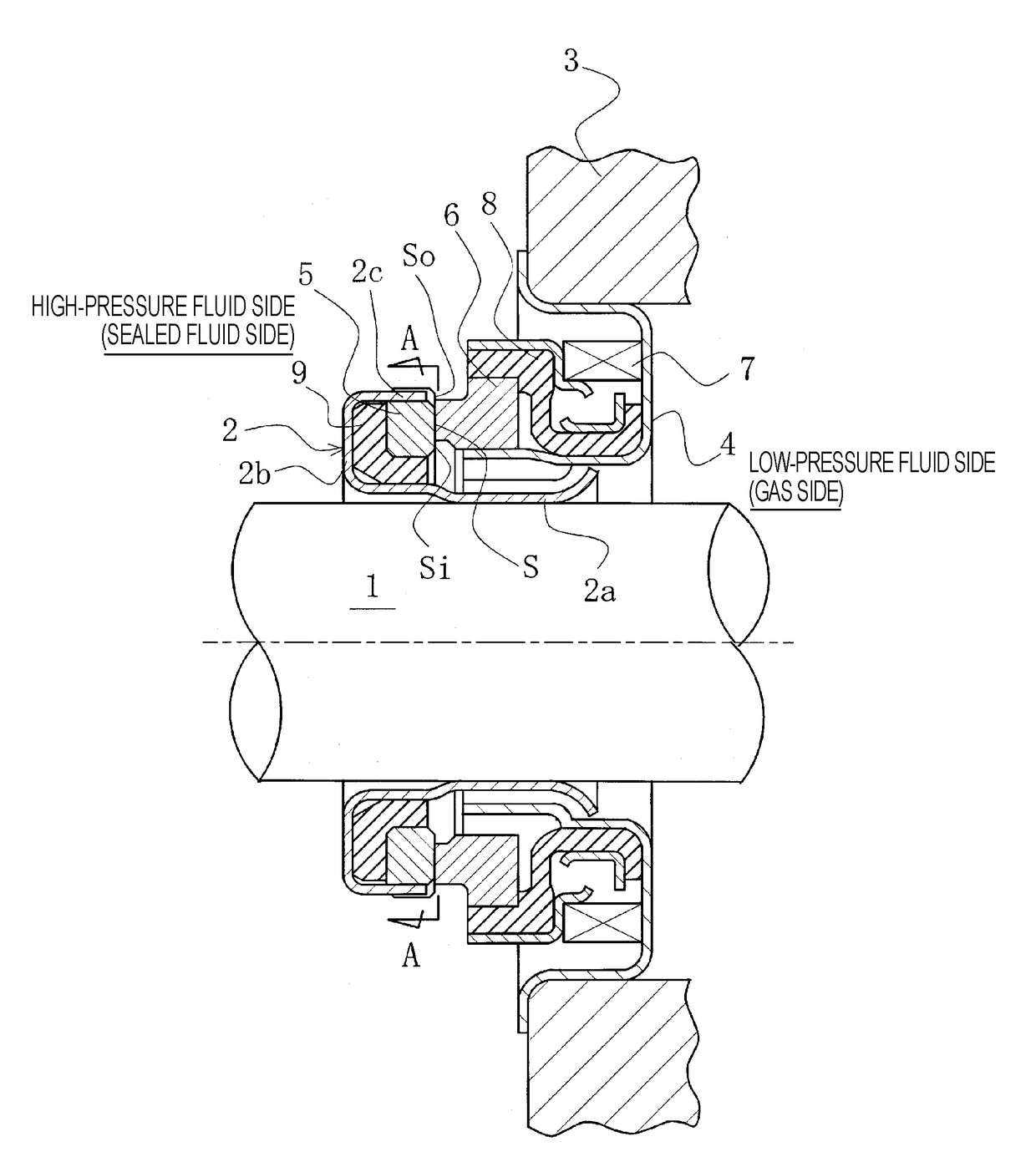
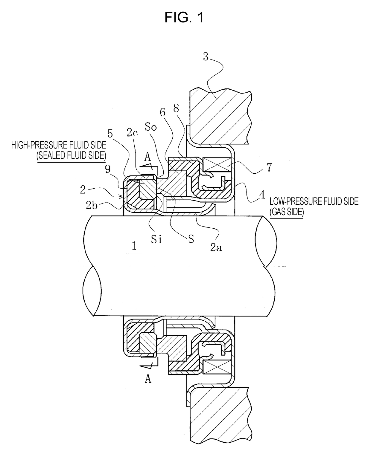
[0022]FIG. 1 is a vertical sectional diagram illustrating an example of the mechanical seal, which is an inside mechanical seal in a form in which a sealed fluid on the high-pressure fluid side which is apt to leak from the outer periphery on the sliding faces toward the inner periphery is sealed. The mechanical seal is provided with a sleeve 2 which is fixed to a rotating shaft 1 for driving a pump impeller (not illustrated) on the high-pressure fluid side and a cartridge 4 whi...

second embodiment

[0058]A description will be given of a sliding component according to a second embodiment of the present invention, with reference to FIG. 3.

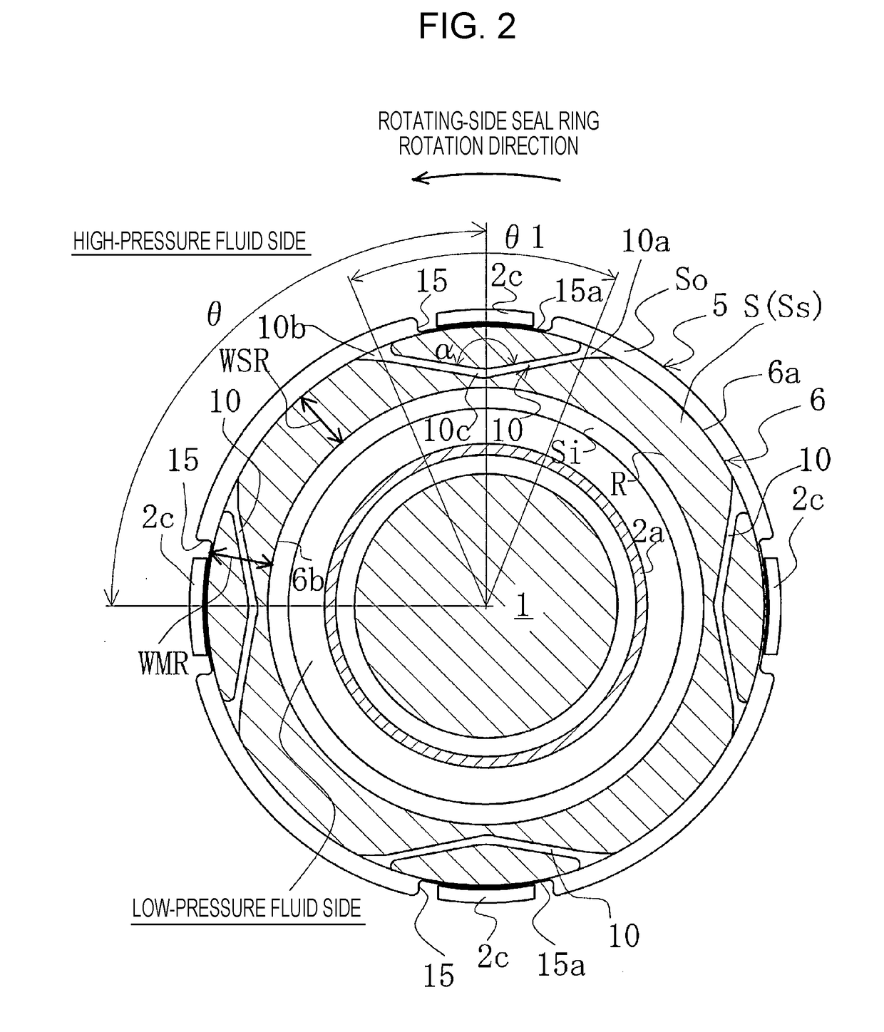
[0059]Although the second embodiment differs from the first embodiment in that the inner diameter of the groove 15 is set to be smaller than the outer diameter 6a of the sliding face of the stationary-side seal ring 6, the other basic configurations of the second embodiment are the same as those of the first embodiment.

[0060]In FIG. 3, the same reference numerals as those in FIG. 2 indicate the same members as those in FIG. 2 and redundant descriptions thereof will be omitted.

[0061]In FIG. 3, the inner diameter of the bottom portion 15a of the groove 15 provided on the outer periphery of the rotating-side seal ring 5, that is, the inner diameter of the groove 15 is set to be smaller than the outer diameter 6a of the sliding face of the stationary-side seal ring 6. WMR / MSR is set to greater than or equal to 0.75, where WMR is the face width defi...


PUM


Abstract

In an embodiment, in a sliding component, a sliding face of a stationary-side seal ring 6 has a fluid circulation groove 10 communicating with a high-pressure fluid side via an entrance portion 10a and an exit portion 10b. A rotating-side seal ring 5 has a larger outer diameter and a smaller inner diameter than the seal ring 6. A groove 15 into which a claw is loosely fitted is provided on an outer periphery of the seal ring 5. A width of the groove 15 is smaller than a distance between the portion 10a and the 10b in the circumferential direction. WMR/WSR is set within a range of 0.75<WMR/WSR<1.4 (WMR is a face width between an inner diameter of the groove 15 and an inner diameter 6b of the sliding face; WSR is a face width of the sliding face).

Description

TECHNICAL FIELD[0001]The present invention relates to sliding components suitable for, for example, mechanical seals, bearings, and other sliding units. In particular, the present invention relates to sliding components such as seal rings or bearings which reduce friction by interposing fluid between sliding faces and need to prevent leakage of fluid from the sliding faces.BACKGROUND ART[0002]In a mechanical seal which is an example of a sliding component, the performance of the mechanical seal is evaluated according to a leakage rate, a wear rate, and torque. In the related art, the sliding material properties and the sliding face roughness of the mechanical seal are optimized to improve the performance, realizing low leakage, long life, and low torque. However, due to the growing awareness of environmental problems in recent years, there is a demand for further improvement in the performance of the mechanical seal and technical development beyond the framework of the related art h...

Claims


Application Information

Patent Timeline
Patent Type & Authority Applications(United States)
IPC IPC(8): F16J15/34F04D29/12F16C33/78F16C33/74F16J15/16
CPCF16J15/3416F04D29/122F16C33/7843F16C33/743F16J15/162F05D2240/55F16J15/3412F16J15/3464
Inventor ITADANI, MASATOSHISUNAGAWA, KAZUMASATOKUNAGA, YUICHIROINOUE, HIDEYUKIHOSOE, TAKESHIYAMAKAWA, RYOMANEGISHI, YUTAKIRYU, KENJICHIBA, KEIICHIYOSHINO, AKIRAKUBOTA, HIROSHI
Owner EAGLE INDS
Why Eureka
Try Eureka