Object multi-perspective inspection apparatus and method therefor

a multi-perspective, object technology, applied in the direction of measuring devices, instruments, optically investigating flaws/contamination, etc., can solve the problems of reducing the inspection rate and elapsed time, and achieve the effect of reducing the effort to inspect every single part from multiple sides and increasing overall quality

Active Publication Date: 2018-07-05
ABB (SCHWEIZ) AG
View PDF35 Cites 1 Cited by
  • Summary
  • Abstract
  • Description
  • Claims
  • Application Information

AI Technical Summary

Benefits of technology

[0006]By introducing reflection devices into the inspection apparatus to enable the image capture device to “see” the part from multiple views at once, multiple surfaces can be inspected at once, in one image frame, without having the need to reposition the reflection device, the camera and / or the object for every single surface. There are more than one reflection devices placed in the camera's field of view to assist the inspection process by exploiting otherwise hidden surfaces of any given solid object. The effort inspecting every single part from multiple sides is reduced. Therefore, the period of the inspection cycle time can be reduced and inspection on the level of multi-surfaces becomes possible increasing overall quality.
[0007]Preferably, the at least two reflection devices are arranged to guide the lights directly from the object; and each of the two reflection devices is inclined by a predetermined angle with respect to an optical axis of the image capture device so that the image capture device receives the reflected side view of the object directly therefrom. Such arrangement of the observation angle makes it possible to place the reflection devices in direct line of sight of the image capture device. Therefore, it provide an economic solution without deploying extra reflection devices.
[0008]Preferably, the at least two reflection devices are arranged for reflecting simultaneously to the image capture device top view of the object located in the inspection site so that the image capture device receives the reflected top view of the object directly therefrom. Therefore, the field of view of the reflection device may be enlarged to cover the top view of object and he controller may conduct the comparison concerning the part relevant to the top view of the object appearing in the images for the top view and the side views. This is advantageous since light falling onto a surface from one side can only reveal a certain set of defects. Provided throughout the mirrors, light does not only fall onto the surface in one direction, but in at least one more angle. These different views of one and the same surface can be seen in the mirrors, leading to a more thorough investigation in only one image frame. In addition, in the image frame the static scene can easily be masked, so that only the areas of interest are analyzed.

Problems solved by technology

A conventional approach is to analyse product samples, surface by surface, which eventually takes long time.
Therefore, a period of the inspection cycle time has to be set long enough to allow the completion of the repositioning of the mirrors for a multi-perspective inspection, which decreases the inspection rate.

Method used


Image

  • Object multi-perspective inspection apparatus and method therefor
  • Object multi-perspective inspection apparatus and method therefor
  • Object multi-perspective inspection apparatus and method therefor

Examples


Embodiment Construction

[0018]In the following description, for purposes of explanation and not limitation, specific details are set forth, such as particular circuits, circuit components, interfaces, techniques, etc. in order to provide a thorough understanding of the present invention. However, it will be apparent to one skilled in the art that the present invention may be practiced in other embodiments that depart from these specific details. In other instances, detailed descriptions of well-known methods and programming procedures, devices, and circuits are omitted so not to obscure the description of the present invention with unnecessary detail.

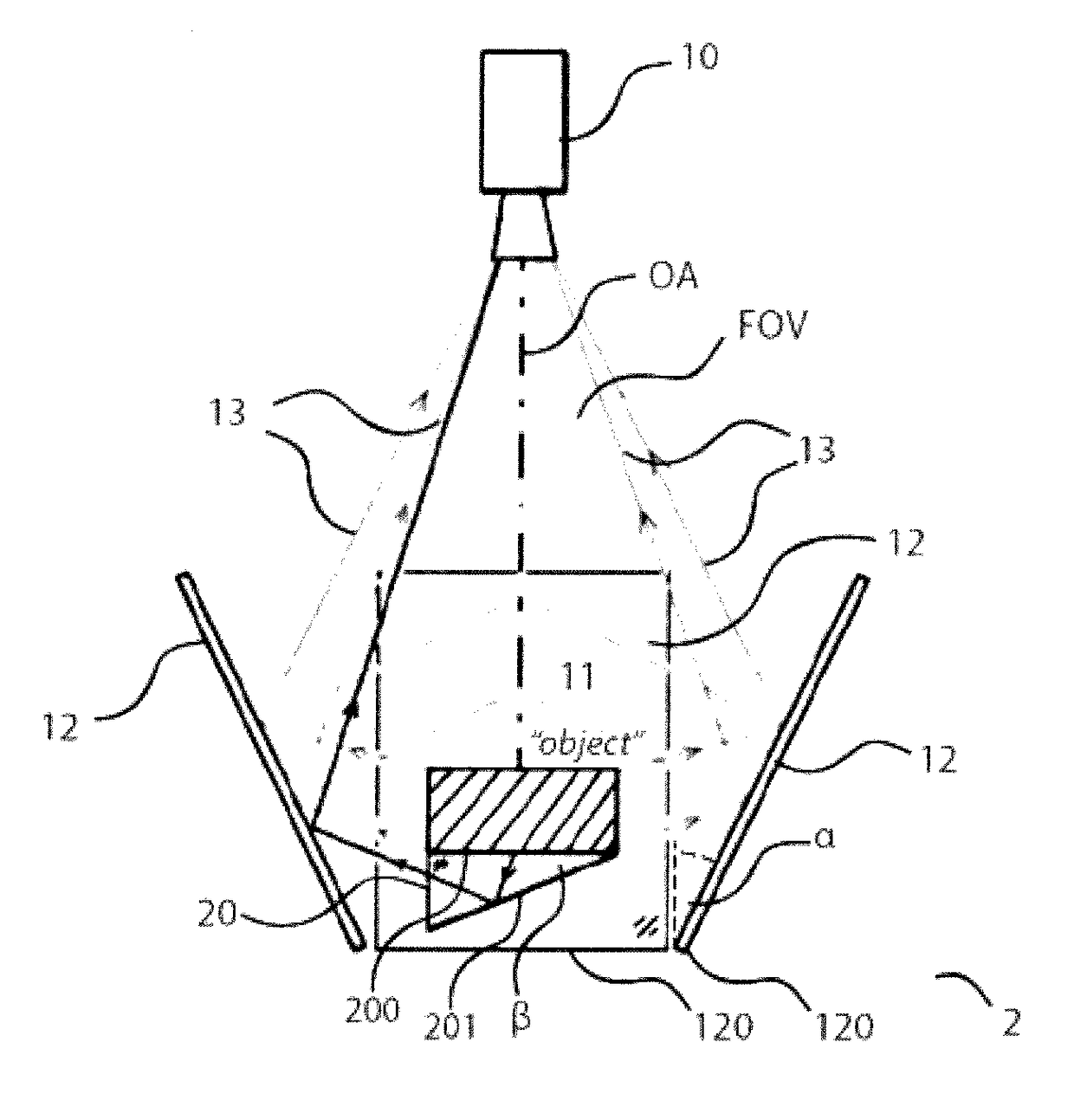
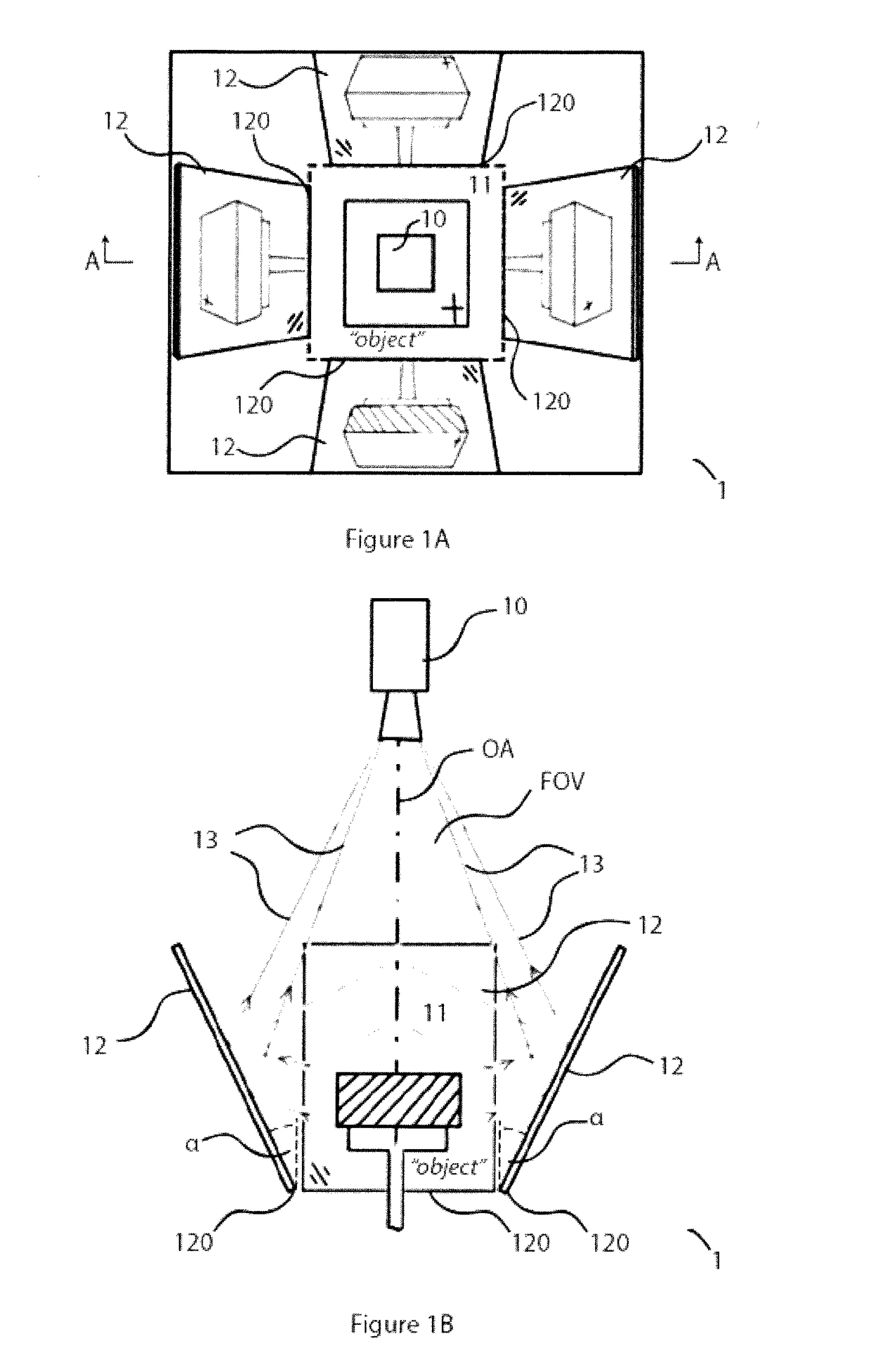
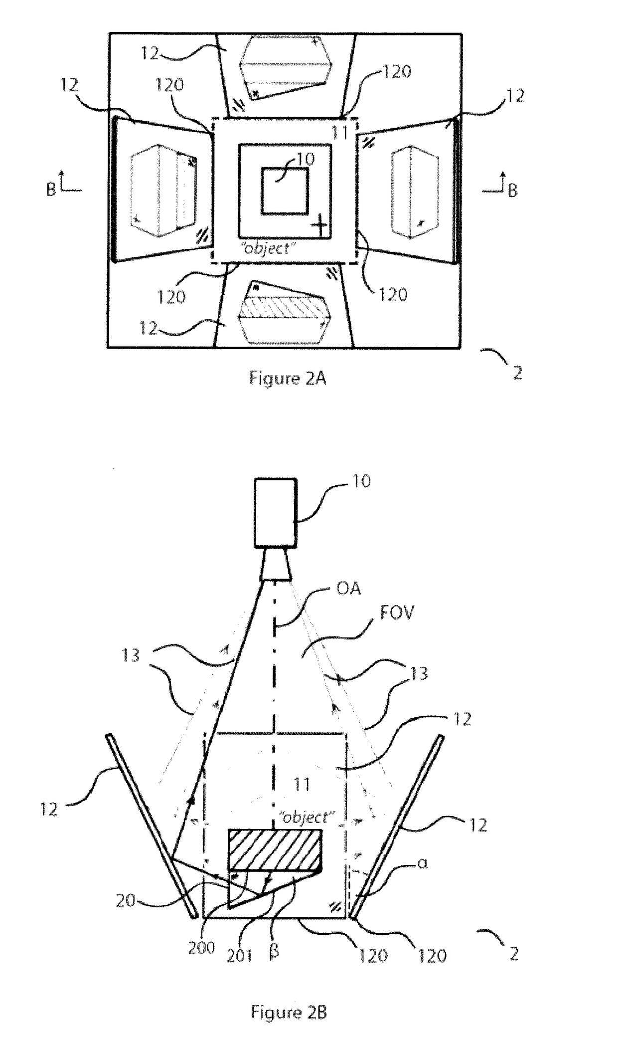
[0019]FIGS. 1A and 1B respectively show an object multi-perspective inspection apparatus according to an embodiment of present invention and its sectional drawing taken along line A-A of FIG. 1A. As shown in FIGS. 1A and 1B, the object multi-perspective inspection apparatus 1 includes an image capture device 10, an inspection site 11 and at least two reflectio...


PUM

PropertyMeasurementUnit
angleaaaaaaaaaa
lengthsaaaaaaaaaa
field of viewaaaaaaaaaa

Abstract

It is therefore an objective to provide an object multi-perspective inspection apparatus and a method therefor. The apparatus includes an image capture device; an inspection site and at least two reflection devices, being arranged for reflecting simultaneously to the image capture device at least two different side views of the object located in the inspection site; wherein: the image capture device has a field of view including the at least two different side views of the reflection. By introducing reflection devices into the inspection apparatus to enable the image capture device to “see” the part from multiple views at once, multiple surfaces can be inspected at once, in one image frame, without having the need to reposition the reflection device, the camera and/or the object for every single surface. There are more than one reflection devices placed in the camera's field of view to assist the inspection process by exploiting otherwise hidden surfaces of any given solid object. The effort inspecting every single part form multiple sides is reduced. Therefore, the period of the inspection cycle time can be reduced and inspection on the level of multi-surfaces becomes possible increasing overall quality.

Description

TECHNICAL FIELD[0001]The invention relates to investigating and analysing object by use of optical means, and more particularly to apparatus for inspecting object from multi-perspective with optical means and method therefor.BACKGROUND ART[0002]Visual cosmetic inspection is commonly used for quality control, data acquisition, and data analysis. This is an important commercial function, which may be used for example, for visually distinguishing between flawed and flawless product from production / manufacturing / assembly processes of 3C industry.[0003]A conventional approach is to analyse product samples, surface by surface, which eventually takes long time. Given a certain throughput rate of any given production process, only a small number of samples can be inspected. In other words, some defective products may be identified as flawless without inspection and reaches the end of the production line. Therefore, the operator has to make a compromise between the production rate and the pr...

Claims


Application Information

Patent Timeline
Patent Type & Authority Applications(United States)
IPC IPC(8): G01N21/88
CPCG01N21/8806G01N2201/0638G01N2201/0636G01B11/24G01N21/95G01N2021/8841G01N21/8803
Inventor KEFER, MARTINZHANG, JIAFAN
Owner ABB (SCHWEIZ) AG
Why Eureka
Try Eureka