RFID tags with shielding structure for incorporation into microwavable food packaging

a technology of shielding structure and rfid tags, which is applied in the direction of packaging foodstuffs, instruments, packaged goods, etc., can solve the problems of failure to take proper care, arc generation, and packaging to catch fire, and achieve greater resistance and limit the voltage across the gap

Active Publication Date: 2018-07-05
AVERY DENNISON CORP
View PDF1 Cites 35 Cited by
  • Summary
  • Abstract
  • Description
  • Claims
  • Application Information

AI Technical Summary

Benefits of technology

[0013]In another aspect, packaging is provided for a microwavable food item. The packaging includes an enclosure and an RFID tag secured to the enclosure. The RFID tag includes an antenna defining a gap and configured to operate at a first frequency. An RFID chip is electrically coupled to the antenna across the gap. A shielding structure is electrically coupled to the antenna across the gap and overlays the RFID chip. The shielding structure includes a shield conductor and a shield dielectric at least partially positioned between the shield conductor and the RFID chip. A second shielding structure is electrically coupled to the antenna across the gap, underlying the RFID chip. The shielding structure is configured to limit the voltage across the gap when the antenna is exposed to a second frequency that is greater than the first frequency.
[0014]In another aspect the antenna comprised of an antenna with a sheet resistance in the range of approximately 100 ohms to approximately 230 ohms. In another aspect, an RFID tag includes an RFID chip and an antenna electrically coupled to the RFID chip. The antenna is comprised of a conductor formed of a base material and a second material with different coefficients of thermal expansion configured to cause the antenna to fracture into multiple pieces upon being subjected to heating.
[0015]In yet another aspect, a package is provided for a microwavable food item. The package includes an enclosure, an RFID label, and a joinder material sandwiched between the RFID label and the enclosure. The RFID label includes a substrate and an RFID tag associated with the substrate. The RFID tag includes an RFID chip and an antenna electrically coupled to the RFID chip. The joinder material has a greater resistance than the antenna.

Problems solved by technology

Due to the absorbing nature of the film used as the susceptor, relatively low levels of energy are reflected by it, such that it does not strike an arc due to generating high differential voltages between adjacent parts of the film, which could otherwise cause the packaging to catch fire.
However, the gap G bridged by the RFID chip C is necessarily relatively small and, hence, a high voltage arises at the second frequency F2, which high voltage may cause a breakdown and generate an arc.
However, it is possible that a user failing to take proper care could place the entire package (including the RFID tag T and 11 shown in FIGS. 1 and 1A respectively) into the microwave oven with the food item, thereby failing to dissociate the RFID tag T or 11 from the food item.

Method used


Image

  • RFID tags with shielding structure for incorporation into microwavable food packaging
  • RFID tags with shielding structure for incorporation into microwavable food packaging
  • RFID tags with shielding structure for incorporation into microwavable food packaging

Examples


Embodiment Construction

[0034]As required, detailed embodiments of the present invention are disclosed herein; however, it is to be understood that the disclosed embodiments are merely exemplary of the invention, which may be embodied in various forms. Therefore, specific details disclosed herein are not to be interpreted as limiting, but merely as a basis for the claims and as a representative basis for teaching one skilled in the art to variously employ the present invention in virtually any appropriate manner.

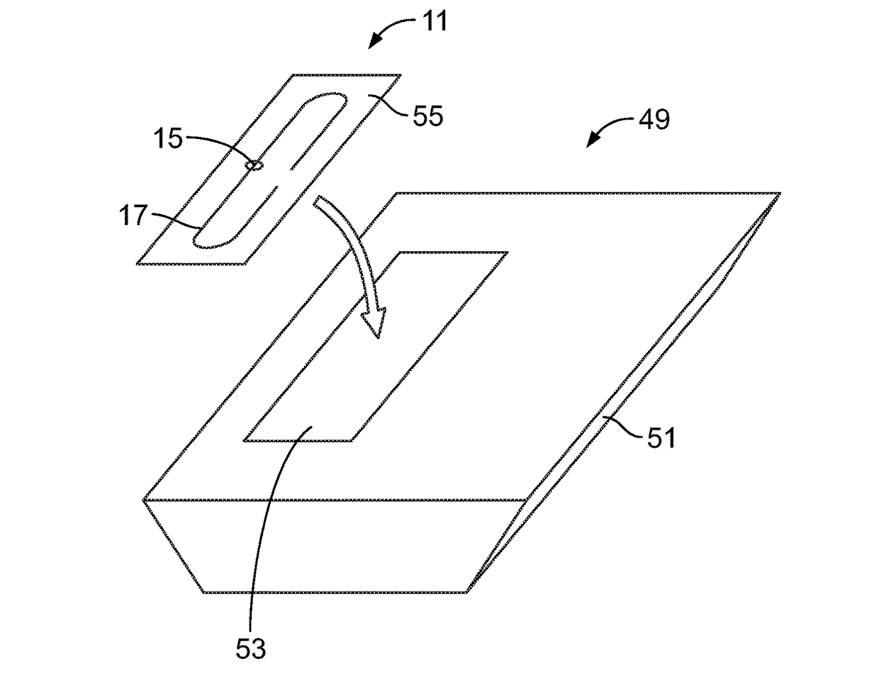
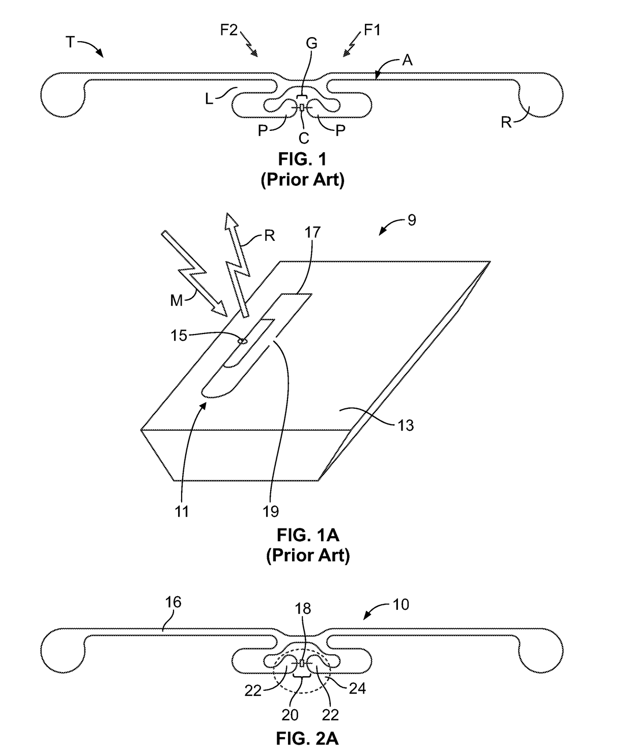
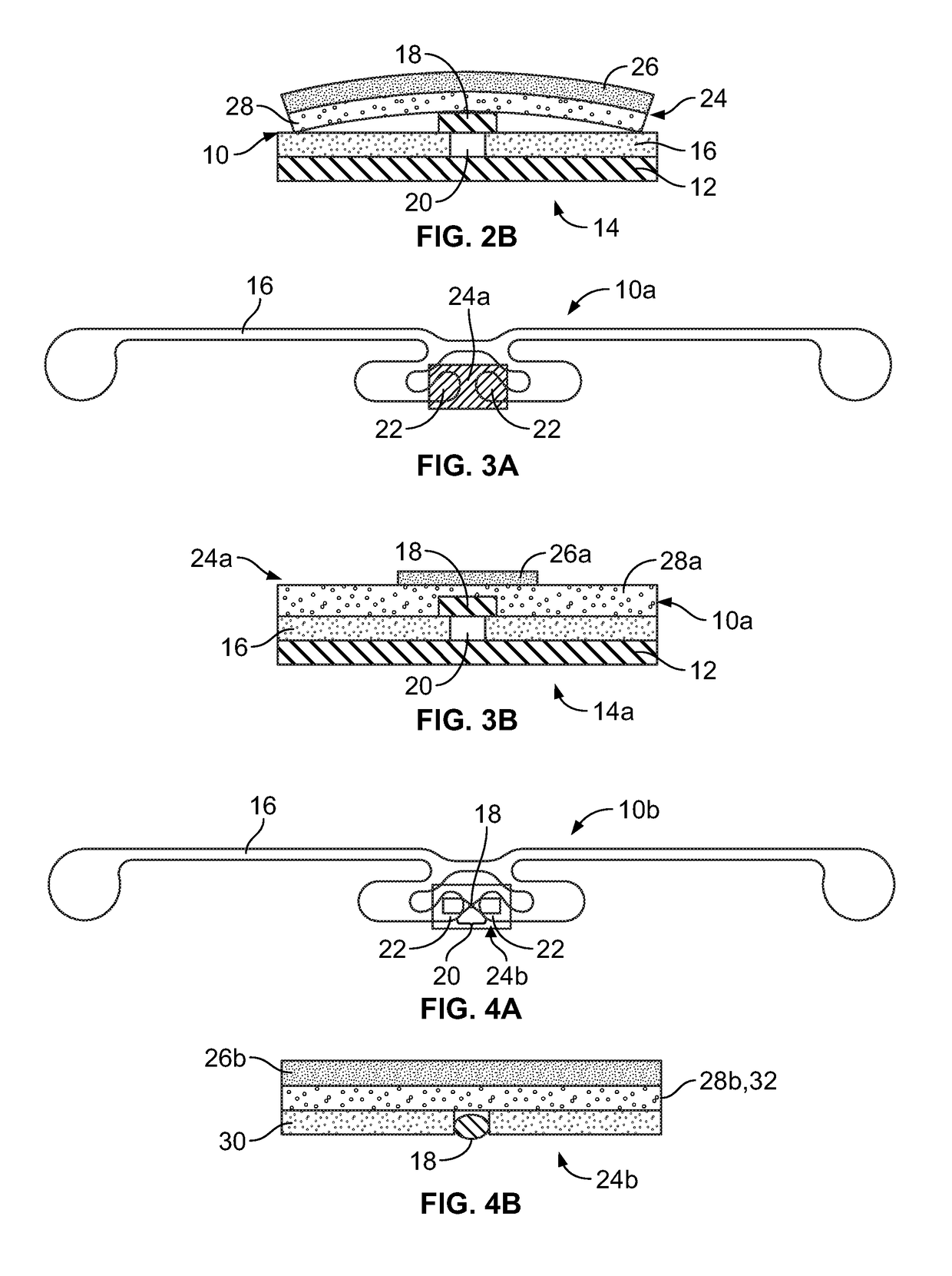
[0035]FIGS. 2A and 2B show an RFID tag 10 according to the present disclosure, while FIG. 2B shows the RFID tag, generally designated at 10, secured to the enclosure 12 (e.g., a paper box) of packaging, generally designated at 14, for a microwavable food item. The packaging 14 may include other items, such as a “crisping sleeve” configured to be microwaved with the food item. The RFID tag 10 may be incorporated into the packaging 14 by any suitable approach and, while the RFID tag 10 is secured to ...


PUM


Abstract

RFID tags are provided for incorporation into the packaging of a microwavable food item, with the RFID tag being configured to be safely microwaved. The RFID tag includes an antenna defining a gap and configured to operate at a first frequency. An RFID chip is electrically coupled to the antenna across the gap. A shielding structure is electrically coupled to the antenna across the gap and overlays the RFID chip. The shielding structure includes a shield conductor and a shield dielectric at least partially positioned between the shield conductor and the RFID chip. The shielding structure is configured to limit the voltage across the gap when the antenna is exposed to a second frequency that is greater than first frequency. In additional embodiments, RFID tags are provided for incorporation into the packaging of a microwavable food item, with the RFID tag being configured to be safely microwaved. The RFID tag includes an RFID chip and an antenna electrically coupled to the RFID chip. The antenna may have a sheet resistance in the range of approximately 100 ohms to approximately 230 ohms, optionally with an optical density in the range of approximately 0.18 to approximately 0.29. Alternatively, or additionally, the antenna may be configured to fracture into multiple pieces upon being subjected to heating in a microwave oven. Alternatively, or additionally, the RFID tag may be incorporated in an RFID label that is secured to the package by a joinder material with a greater resistance than that of the antenna, such as a sheet resistance in the range of approximately 100 ohms to approximately 230 ohms.

Description

CROSS REFERENCE TO RELATED APPLICATION(S)[0001]The present application claims priority to and the benefit of U.S. Provisional Patent Application No. 62 / 440,108 filed Dec. 29, 2016 and U.S. Provisional Patent Application No. 62 / 539,817 filed Aug. 1, 2017, each of which is incorporated herein by reference in its entirety.BACKGROUNDField of the Disclosure[0002]The present subject matter relates to packaging for microwavable food items. More particularly, the present subject matter relates to radio frequency identification (“RFID”) tags incorporated into packaging for microwavable food items.Description of Related Art[0003]It is known for packages for microwavable food items to include cooking aids that are to be placed into the microwave oven with the food item for cooking / heating the food item. For example, foods having crusts, such as frozen pies or stuffed bread, may benefit from “crisping sleeves,” which are paper items that at least partially surround the food item during microwav...

Claims


Application Information

Patent Timeline
Patent Type & Authority Applications(United States)
IPC IPC(8): G06K19/077G06K19/07B65D81/34
CPCG06K19/0773G06K19/0723G06K19/07771G06K19/07775B65D81/3453B65D2203/10G06K19/07773B65D81/3446G06K19/0715G06K19/07752G06K19/07786G06K19/07798
Inventor FORSTER, IAN J.HOWARD, NORMANCUMBY, BRADORLOWSKI, JAMESSTROHMEIER, BRIANDUAN, HUHIGGINS, CAMERONFELTZ, JOHN
Owner AVERY DENNISON CORP
Why Eureka
Try Eureka