
Operating Doubly-Fed Induction Generators as Virtual Synchronous Generators

a technology of induction generator and double-fed induction generator, which is applied in the direction of electric generator control, machines/engines, mechanical equipment, etc., can solve the problems of full control of the total power, time-consuming design and slow performance, and the plls suffer from nonlinear structure, etc., to achieve high voltage level, reduce system cost, size, weight and loss, and high thermal capacity

Pending Publication Date: 2018-07-05
ZHONG QINGCHANG
View PDF5 Cites 47 Cited by
  • Summary
  • Abstract
  • Description
  • Claims
  • Application Information

AI Technical Summary

Benefits of technology

The invention enables DFIG-based wind turbines to have the benefits of PMSG-based wind turbines while still being cost-effective, smaller, and more efficient. This is important because as wind turbines become larger, the use of full-scale power converters is becoming more limited. The invention allows for a solution that can continue using partial-scale power electronic converters and have direct medium- or high-voltage connection with the grid, saving cost, reducing size and weight, and improving efficiency and reliability.

Problems solved by technology

However, it does not have the full control over the total power, which may cause problems.
However, this control method cannot effectively utilize the mechanical inertia stored in the turbine shaft, which causes problems to the grid stability when the penetration of wind energy becomes high.
However, it has been known that PLLs suffer from nonlinear structure, time-consuming design and slow performance.
What is even worse is that PLLs could cause wind energy systems out of synchrony and lead to instability.
Another concept is called virtual inertia, which is also able to provide frequency regulation but the implementation of the virtual inertia and frequency regulation requires the information of the grid frequency and the rate of change of frequency (ROCOF), which could not avoid the use of a PLL and could lead to poor performance because of the noises introduced in calculating the ROCOF.

Method used


Image

  • Operating Doubly-Fed Induction Generators as Virtual Synchronous Generators
  • Operating Doubly-Fed Induction Generators as Virtual Synchronous Generators
  • Operating Doubly-Fed Induction Generators as Virtual Synchronous Generators

Examples


Embodiment Construction

[0014]The particular values and configurations discussed in these non-limiting examples can be varied and are cited merely to illustrate at least one embodiment and are not intended to limit the scope thereof.

[0015]The embodiments will now be described more fully hereinafter with reference to the accompanying drawings, in which illustrative embodiments of the invention are shown. The embodiments disclosed herein can be embodied in many different forms and should not be construed as limited to the embodiments set forth herein; rather, these embodiments are provided so that this disclosure will be thorough and complete, and will fully convey the scope of the invention to those skilled in the art.

[0016]The terminology used herein for the purpose of describing particular embodiments only and is not intended to be limiting of the invention. As used herein, the singular forms “a,”“an,” and “the” are intended to include the plural forms as well, unless the context clearly indicates otherwi...


PUM


Abstract

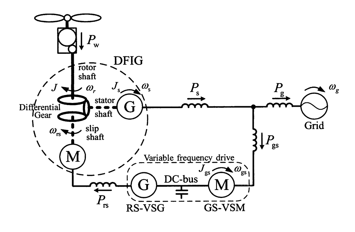
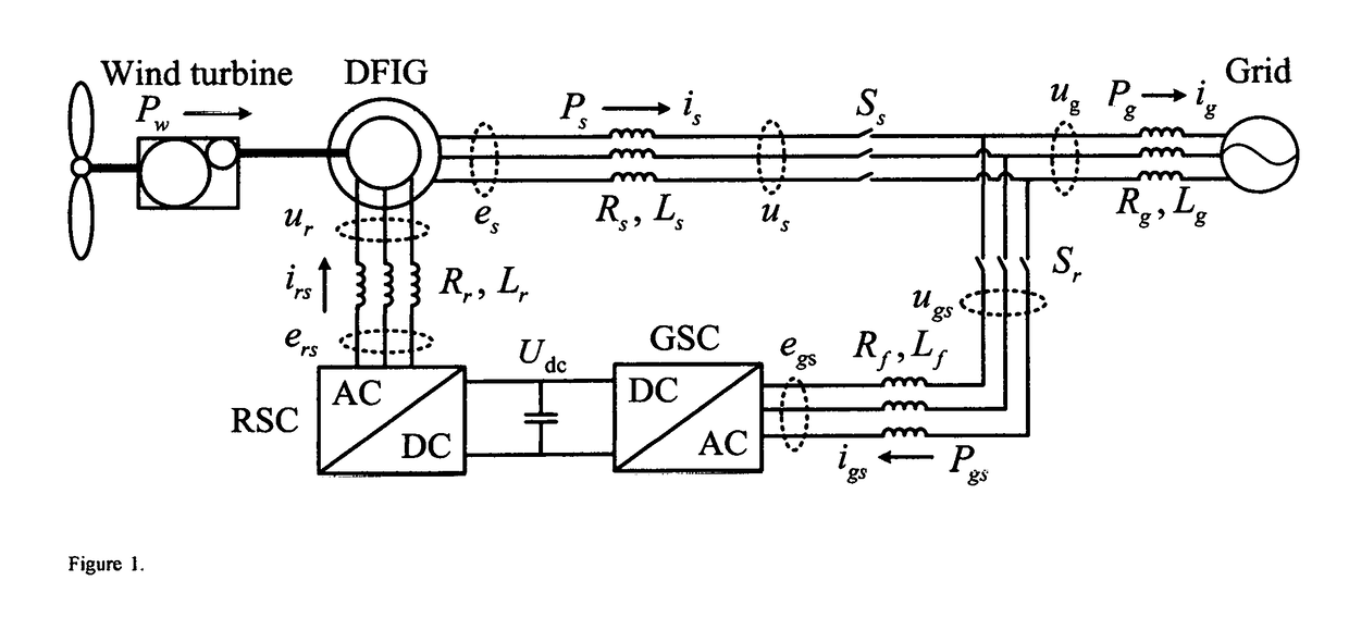
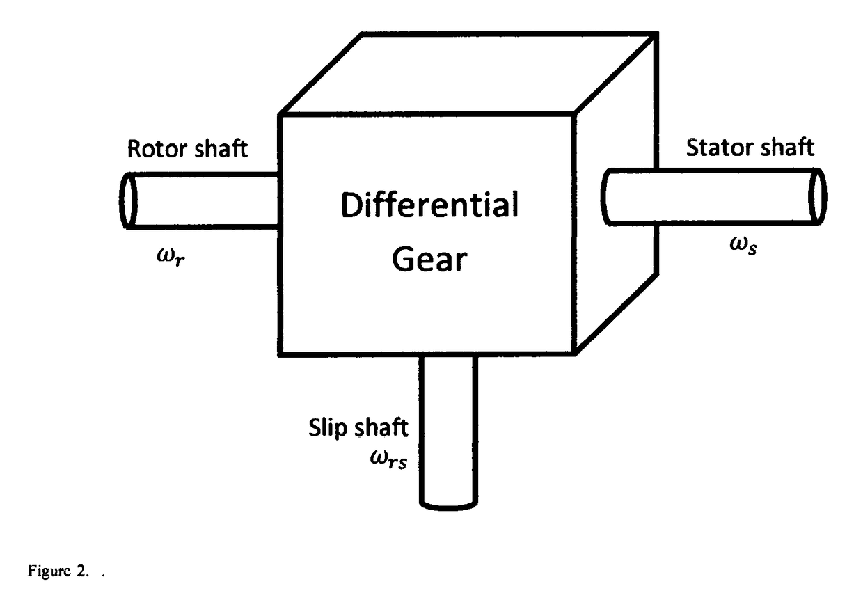
This invention discloses a system and method to operate a doubly-fed induction generator (DFIG) as a grid-friendly virtual synchronous generator (VSG). It comprises a DFIG modeled as a virtual differential gear that links a rotor shaft driven by a prime mover, a virtual stator shaft coupled with a virtual synchronous generator G and a virtual slip shaft coupled with a virtual synchronous motor M, and a variable frequency drive that behaves as a virtual synchronous motor-generator set to regulate the speed of the virtual synchronous motor M so that the speed of the virtual stator shaft, i.e., the speed of the virtual synchronous generator G, is within a narrow band around the grid frequency even when the rotor shah: speed changes. As a result, a grid-connected DFIG can be controlled to behave like a virtual synchronous generator without using a PLL.

Description

CROSS-REFERENCE TO RELATED APPLICATIONS[0001]This nonprovisional patent application claims the benefit of and priority under 35 U.S. Code ğ 119 (b) to U.K. Patent Application No. GB1617589.5 filed on Oct. 17, 2016, entitled “Operating Doubly-Fed Induction Generators as Virtual Synchronous Generators”, the contents of which are all hereby incorporated by reference herein in its entirety.TECHNICAL FIELD[0002]This invention is concerned with control devices and control methods that operate a doubly-fed induction generator (DFIG) as a virtual synchronous generator (VSG). Possible application fields include smart, grid, renewable energy, such as wind energy and wave enemy, and aircraft power systems etc. Here, the application to wind energy is taken as an example.BACKGROUND[0003]Wind energy has been regarded as a major means to combat the energy crisis and sustainability issues. In recent years, the technology of wind energy generation has undergone tremendous development. Variable-speed...

Claims


Application Information

Patent Timeline
IPC IPC(8): H02P9/00H02J3/18F03D7/02F03D9/25
CPCH02P9/007H02J3/1885F03D7/0272F03D9/25H02P2101/15H02J2300/28H02J3/381Y02E10/76Y02E10/72H02J3/40H02J3/50
Inventor ZHONG, QINGCHANG
Owner ZHONG QINGCHANG
Learn More