Coolable wall element with impingement plate

Active Publication Date: 2018-07-12
SIEMENS ENERGY GLOBAL GMBH & CO KG
View PDF4 Cites 0 Cited by
  • Summary
  • Abstract
  • Description
  • Claims
  • Application Information

AI Technical Summary

Benefits of technology

The invention relates to a coolable wall for a gas turbine engine and an improved design for the impingement plate used in the coolable wall. The invention provides a more easily removable impingement plate for repair and refurbishment of the coolable wall element, reducing assembly costs and manufacturing time. The impingement plate can be easily removed and reinstalled for inspecting and cleaning the coolable wall element. The method of assembling the impingment plate onto the base body involves inserting the impingment plate into grooves on the base body and using a bendable retention tab to secure the impingment plate in place. The invention also allows for easy disassembly of the impingment plate from the base body for repair or replacement. Overall, the invention simplifies the process of maintaining the coolable wall and improves the overall performance of the gas turbine engine.

Problems solved by technology

The provision of these folded edges seems expensive.

Method used


Image

  • Coolable wall element with impingement plate
  • Coolable wall element with impingement plate
  • Coolable wall element with impingement plate

Examples


Embodiment Construction

[0029]In all figures identical features will have assigned with same reference numbers.

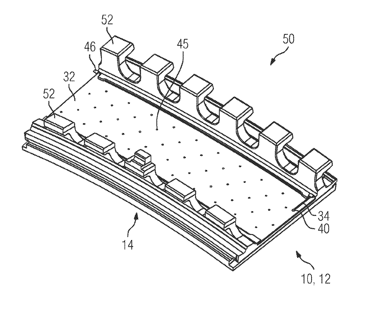
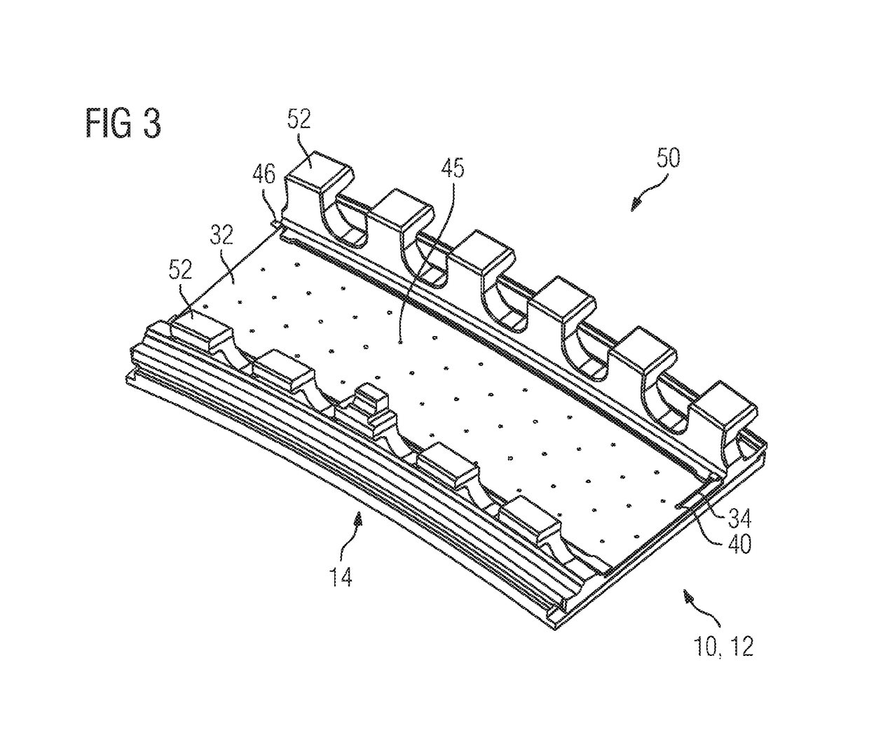
[0030]The explanation of the invention is made with the aid of a ring segment of a gas turbine. Nevertheless the coolable wall element 10 according to the invention could be applied also on other devices of a gas turbine. Other devices could be also the platform of a turbine vane which is also cooled by impingement cooling, a turbine blade attachable to a rotor of a gas turbine or an impingement cooled wall element of a combustor shell.

[0031]FIG. 3 displays in a perspective view a ring segment 50 as a coolable wall element 10 comprising a base body 12 and a removable attached impingement plate 32. Hooks 52 located in the cold side of the base body 12 are used to attach the ring segment to a turbine vane carrier (not shown).

[0032]FIG. 1 displays only the base body 12, which comprises a first surface 14, which is subjectable to a hot gas, when the coolable wall element is assembled in a gas turbine....


PUM


Abstract

A coolable wall element for a gas turbine, having a base body with a first surface subjectable to a hot gas, second surface arranged opposite of the first surface, and first seat for housing edges of an impingement plate. The wall element has an impingement plate partly inserted into the first seat located at a distance and adjacent to the second surface. A coolable wall element with extended life time is provided with the impingement plate which is removably attached to the base body having a snap-in connection with a bendable retention tab extending from the rest of the impingement plate to a free end of the retention tab, wherein the base body has a second seat for the free end of said tab, the second seat blocks the moving of the impingement plate relative to the main body when the bendable retention tab is released.

Description

CROSS REFERENCE TO RELATED APPLICATIONS[0001]This application is the US National Stage of International Application No. PCT / EP2016 / 066772 filed Jul. 14, 2016, and claims the benefit thereof. The International Application claims the benefit of European Application No. EP15176873 filed Jul. 15, 2015. All of the applications are incorporated by reference herein in their entirety.FIELD OF INVENTION[0002]The invention relates to an impingement coolable wall element for a gas turbine, comprising a base body having a first surface subjectable to a hot gas, a second surface which is arranged opposite of the first surface and a first seat for a housing edges of an impingement plate, the wall element further comprising an impingement plate partly inserted into the first seat, located at a distance and adjacent to the second surface. The invention relates also to a method for assembling / disassembling an impingement plate onto / from the base body of a coolable wall, providing a base body having ...

Claims


Application Information

Patent Timeline
IPC IPC(8): F01D25/12F01D5/18F01D9/04F01D25/24F23R3/16
CPCF01D25/12F01D5/187F01D9/041F01D25/246F23R3/16F05D2220/32F05D2230/64F05D2260/201F23R2900/03044F01D11/12F05D2240/11F05D2260/38F05D2300/501F05D2230/70Y10T29/49863Y10T29/49869Y10T29/49318Y10T29/49323Y10T29/49867Y10T29/4987
Inventor SMITH, REXWILLIAMS, MICHAEL
Owner SIEMENS ENERGY GLOBAL GMBH & CO KG
Why Eureka
Try Eureka