Current detection device

a current detection and detection device technology, applied in measurement devices, instruments, electrical measurements, etc., can solve the problems of deterioration of feedback coils and shield layers, affecting the boundary of heat stress, and cracking at the stepped portions of the upper insulating layer, so as to prevent the partial concentration of heat stress, reduce the dynamic range of current to be measured, and reduce the saturated magnetization

Active Publication Date: 2018-07-12
ALPS ALPINE CO LTD
View PDF0 Cites 2 Cited by
  • Summary
  • Abstract
  • Description
  • Claims
  • Application Information

AI Technical Summary

Benefits of technology

[0022]In the current detection device according to the present invention, a coil layer including a plurality of segments arranged in a helical pattern and a height adjustment layer disposed on both sides of the coil layer are covered with an upper insulating layer made of an inorganic material, and a shield layer is disposed on the upper insulating layer so as to cover both the coil layer and the height adjustment layer. Thus, stepped portions can be prevented from being formed at the bonding boundary between the upper insulating layer and the shield layer on both side portions of the coil layer including the plurality of segments. Even if heat stress is produced between the upper insulating layer and the shield layer, partial concentration of the heat stress can be prevented, and a crack is less likely to be produced in the upper insulating layer.
[0023]The shield layer can be formed into a substantially flat shape. Thus, a decrease in saturated magnetization in the shield layer in a sensitive-axis direction of the magnetic detector can be prevented, and a decrease in the dynamic range of a current to be measured can be prevented. Furthermore, since the shield layer can be formed into a substantially flat shape, the linearity of a detection output can be increased.

Problems solved by technology

However, the organic insulating layer, which is hygroscopic, may deteriorate the feedback coil and the shield layer that are in contact with the upper insulating layer.
However, if the insulating layer made of an inorganic material is formed by using chemical vapor deposition (CVD) or spattering, relatively large stepped portions are inevitably produced at a surface of the upper insulating layer, from an upper surface of a coil layer constituting the feedback coil to both outer sides of the coil layer at both side portions of the feedback coil, because the coil layer has a relatively large height.
Thus, heat stress is likely to affect the boundary between the upper insulating layer and the shield layer during a cooling process after each heating process.
In such a multilayer structure, the heat stress between the upper insulating layer and the shield layer concentrates on the stepped portion of both the layers, and the concentration of stress is likely to cause a crack at the stepped portions of the upper insulating layer.

Method used


Image

  • Current detection device
  • Current detection device
  • Current detection device

Examples


examples

[0078]The anisotropic magnetic field Hk in the Y direction was measured by using the shield layers 3 and 103 illustrated in FIGS. 7A and 7B, respectively.

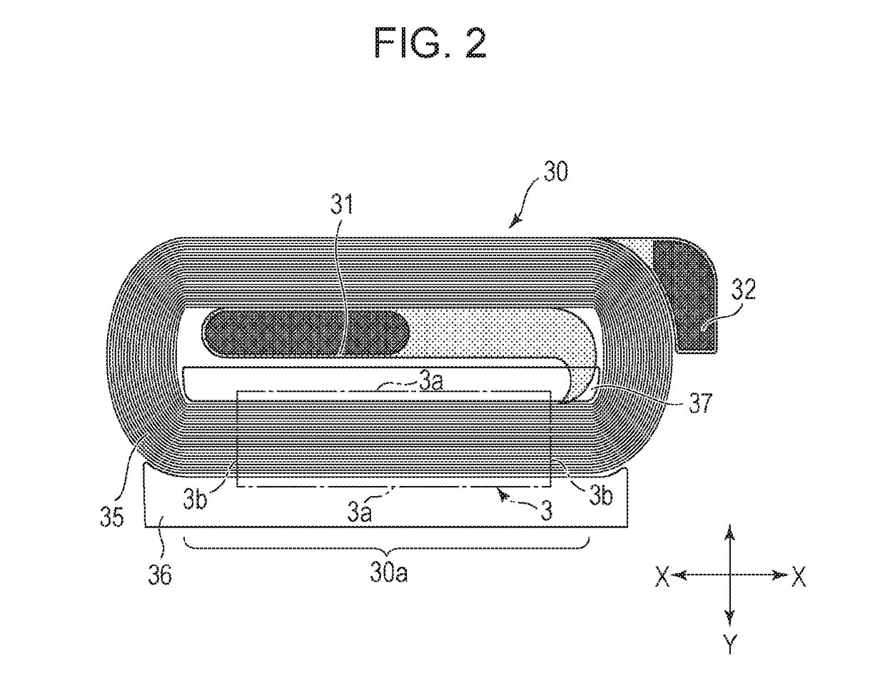
[0079]The shield layers 3 and 103 are plated layers made of Ni—Fe alloy. The alloy composition is 80% by mass of Ni and 20% by mass of Fe. The shield layers 3 and 103 both have a thickness t of 16.5 μm. The shield layer 3 according to the embodiment of the present invention illustrated in FIG. 7A includes side portions 3a extending in the longitudinal direction (X direction) and end portions 3b extending in the lateral direction (Y direction). The width Ws in the lateral direction (Y direction) is 0.14 mm, and the length Ls in the longitudinal direction (X direction) is 0.81 mm. In the shield layer 103 according to the comparative example illustrated in FIG. 7B, a width Wc in the lateral direction is 0.14 mm, and a length Lc in the longitudinal direction is 0.81 mm. The shield layer 103 according to the comparative example includes...


PUM


Abstract

Magnetic detectors and a lower insulating layer covering the magnetic detectors are disposed on a substrate. On the lower insulating layer, a coil layer including a plurality of segments forming a counter detector of a feedback coil is disposed. Height adjustment layers are disposed on both sides of the coil layer. The coil layer and the height adjustment layers are covered with an upper insulating layer, and a shield layer is disposed thereon. Accordingly, the shield layer can be made substantially flat.

Description

CLAIM OF PRIORITY[0001]This application is a Continuation of International Application No. PCT / JP2016 / 074284 filed on Aug. 19, 2016, which claims benefit of Japanese Patent Applications No. 2015-202698 filed on Oct. 14, 2015 and No. 2016-058282 filed on Mar. 23, 2016. The entire contents of each application noted above are hereby incorporated by reference.BACKGROUND OF THE INVENTION1. Field of the Invention[0002]The present invention relates to a current detection device of a so-called magnetic balance type including a feedback coil.2. Description of the Related Art[0003]Japanese Unexamined Patent Application Publication No. 2013-53903 describes an invention related to a current detection device of a so-called magnetic balance type.[0004]In this current detection device, a magnetoresistive element and a feedback coil face a conductor through which a current to be measured passes. A current magnetic field excited by the current that is to be measured and that flows through the conduc...

Claims


Application Information

Patent Timeline
Patent Type & Authority Applications(United States)
IPC IPC(8): G01R15/20
CPCG01R15/205
Inventor ICHINOHE, KENJISAKAZUME, NAOKIGOTO, MITSUHIROIDE, YOSUKEHATAYA, HIDENORIKAWASAKI, HIDEAKITAKAHASHI, AKIRANISHIYAMA, YOSHIHIRO
Owner ALPS ALPINE CO LTD
Why Eureka
Try Eureka